This helps you quickly interpret patents by identifying the three key elements:
Problems solved by technology
Method used
Benefits of technology
Problems solved by technology
[0015] However, in the conventional structure, there was a problem that the backing layer 4 would become thick anyway.
In addition, even in the case where a heat dissipating block is provided on the back side of the backing layer 4 in order to reduce the thickness of the backing layer 4, a heat dissipating block is required in addition to the backing layer 4, so it is necessary to reduce the thickness for attenuating ultrasonic waves. The overall thickness of the structure is very difficult
Furthermore, in the case of using a heat slug, an additional member different from the backing layer is required, which raises the problem of an increase in the cost of manufacturing the ultrasonic probe.
Method used
Image
Click on the blue label to locate the original text in one second.
Reading with bidirectional positioning of images and text.
Examples
Embodiment approach 1
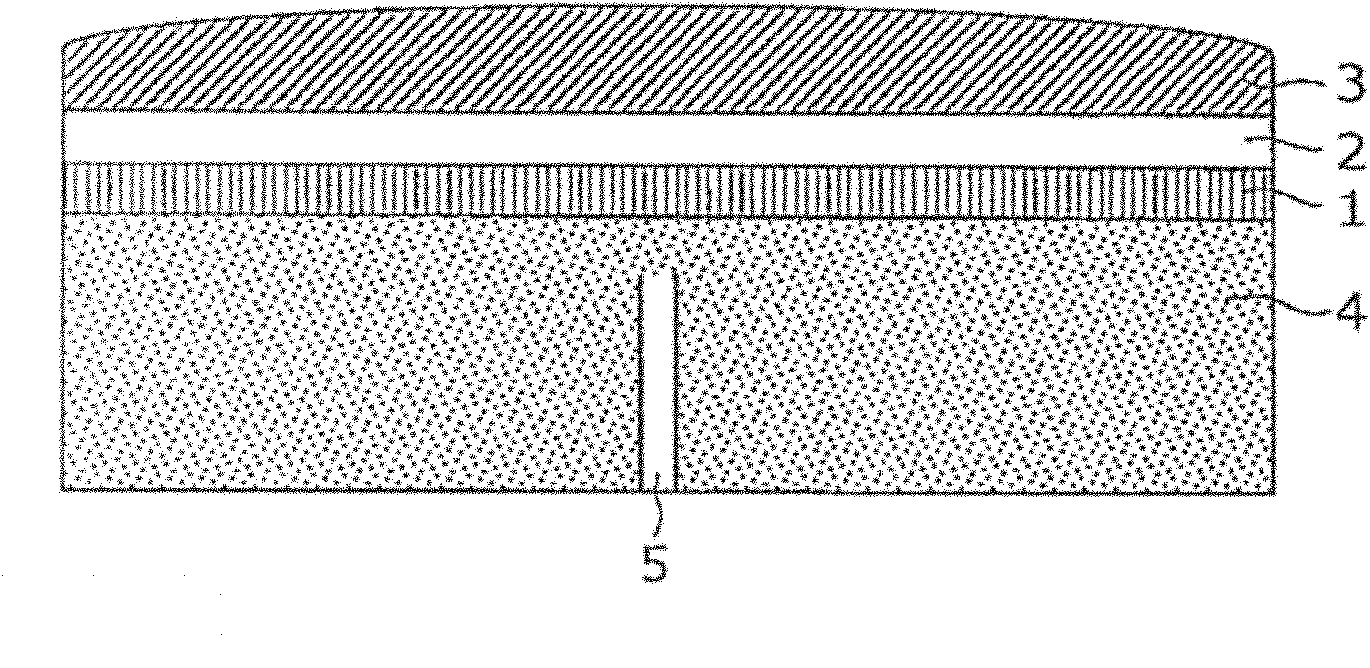
[0042] image 3 It is a cross-sectional view showing the ultrasonic probe in Embodiment 1 of the present invention. like image 3 As shown, the ultrasonic probe according to the first embodiment includes a piezoelectric vibrator 1 , a coupling layer 2 , an acoustic lens 3 , and a backing layer 4 .
[0043] like image 3 As shown, in the ultrasonic probe according to this embodiment, the acoustic tube 5 is arranged inside the backing layer 4 . The acoustic tube 5 has a width sufficiently smaller than the wavelength of the ultrasonic wave radiated from the piezoelectric vibrator 1 and is formed in such a length that the generation of the ultrasonic wave between the direct wave and the reflected wave cancels out.
[0044] For example, when the backing layer 4 is made of epoxy resin, if an ultrasonic wave of f=5 MHz is radiated from the piezoelectric vibrator 1 , the wavelength λ in the backing layer 4 can be obtained using Equation 1.
[0045] [Formula 1]
[0046] ...
Embodiment approach 2
[0050] Figure 4 It is a sectional view of the backing layer 4 in Embodiment 2 of this invention. A plurality of acoustic tubes 5 are disposed inside the backing layer 4 .
[0051] Figure 5It is a cross-sectional view showing an example of the arrangement of the acoustic tubes 5 in Embodiment 2, and in this figure, an example of the backing layer in which the acoustic tubes 5 are arranged based on the square remainder sequence is shown. The length Ln of each acoustic tube is determined by a one-dimensional square remainder sequence shown in Equation 2 below.
[0052] [Formula 2]
[0053] Ln = c · n 2 ( mod N ) 2 Nωr ...(Formula 2)
[0054] Here, c is the speed of sound, N is a prime number, n is an integer varying from 0 to (N-1), and ωr i...
Embodiment approach 3
[0064] In order to realize the backing layer 4 according to the third embodiment, based on the first embodiment, a 250 μm undulation is formed on the substrate by precision printing. Wherein, the length direction of the sound tube corresponds to the thickness direction of the printed ink. Figure 14A It is a flowchart showing the formation procedure of the backing layer by screen printing. Specifically, first, a mask for screen printing adjusted to obtain a dry thickness of 250 μm is formed on a substrate ( S1401 ). Next, a resist film for printing a predetermined pattern is formed (S1402), and a high-resistance material such as a conductive paste using metal is poured in as a paste to perform printing (S1403). Thus, pores are formed on the substrate. In addition, here, the thickness of the printed paste needs to be kept below 250 μm. By satisfying the above-mentioned conditions, the straightness of the sound wave relative to the pores is good, and a good effect can be obtai...
PUM
Abstract
A highly sensitive ultrasonic probe is provided by effectively damping the ultrasonic wave emitted from a piezoelectric oscillator (1) toward the back surface by means of a backing layer (4) and reducing the reflected wave returning to the piezoelectric oscillator (1) side. The thickness of the backing layer (4) is reduced to a value much smaller than conventional. The ultrasonic probe is provided with a piezoelectric oscillator (1) for generating an ultrasonic wave and a backing layer (4) joined to the back surface of the piezoelectric oscillator (1) and adapted for damping the ultrasonic wave which is emitted toward the back surface of the piezoelectric oscillator (1) and has an opposite phase to the phase of the ultrasonic wave emitted toward the front surface of the piezoelectric oscillator (1). In the backing layer (4), a plurality of sound tubes (5) having different lengths on the basis of the principle of sound wave superposition are arranged in such a way that the longitudinal direction of the sound tubes (5) agrees with the directions in which the ultrasonic waves generated from the piezoelectric oscillator (1) travel toward the front and back surfaces. The sound tubes (5) damp the whole or part of the ultrasonic wave emitted by the piezoelectric oscillator (1) to the backing layer (4) side.
Description
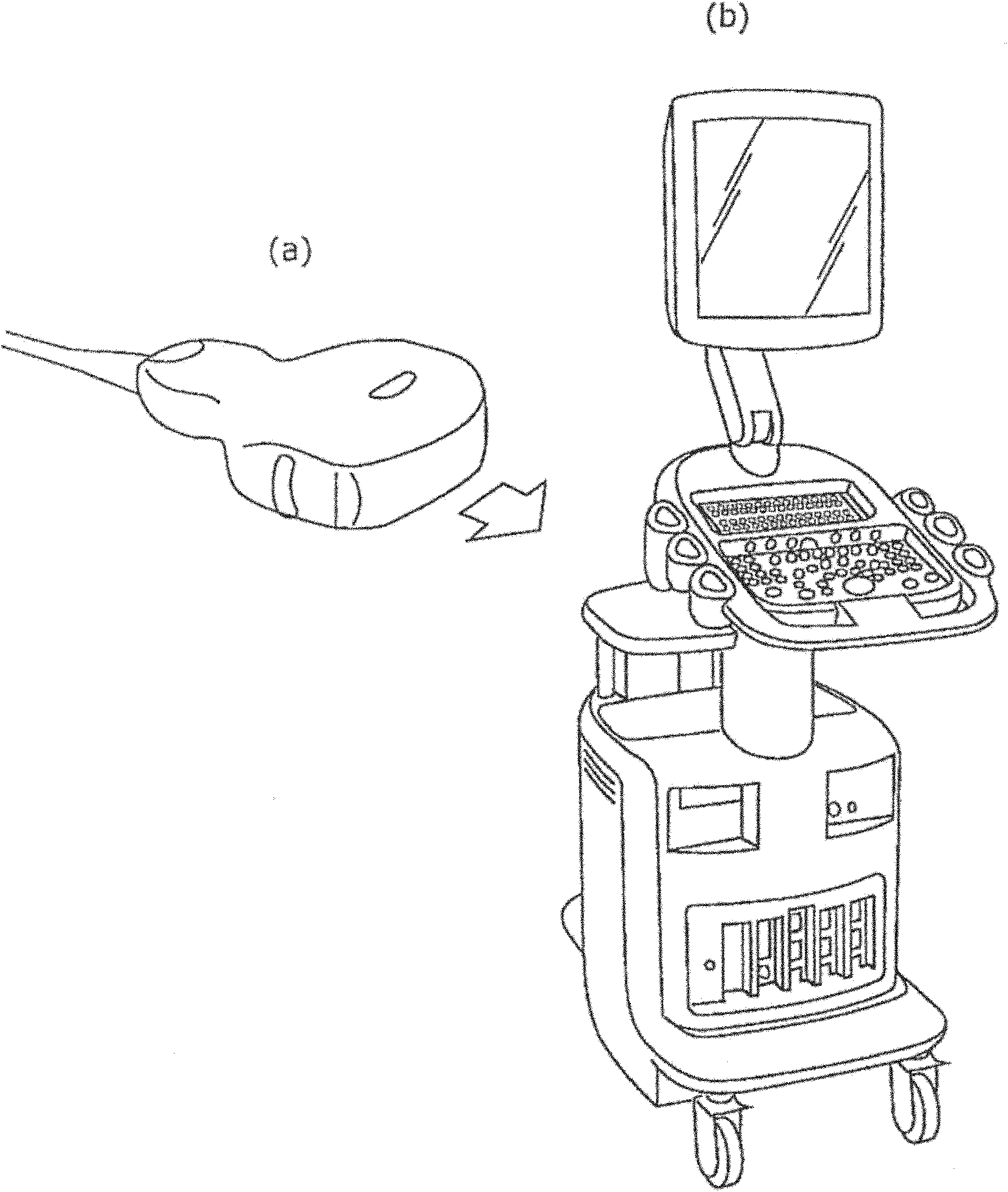
technical field [0001] The present invention relates to an ultrasonic probe for ultrasonic diagnosis. Background technique [0002] figure 1 It is a figure which shows an example of the external appearance of an ultrasonic probe and an ultrasonic diagnostic apparatus. like figure 1 As shown in (a), the ultrasonic probe is connected to the ultrasonic diagnostic device through a cable, transmits ultrasonic waves in the direction of the arrow in the figure, and receives the reflected wave reflected by the living body in the opposite direction to the arrow. like figure 1 As shown in (b), the ultrasonic diagnostic apparatus performs image analysis on reflected waves received by the ultrasonic probe, and displays the image of the inside of the living body obtained by the analysis on a monitor. [0003] In such an ultrasonic probe, when ultrasonic waves are transmitted from the piezoelectric vibrator, the ultrasonic waves are radiated not only to the front of the vibrator but a...
Claims
Application Information
Patent Timeline
Application Date:The date an application was filed.
Publication Date:The date a patent or application was officially published.
First Publication Date:The earliest publication date of a patent with the same application number.
Issue Date:Publication date of the patent grant document.
PCT Entry Date:The Entry date of PCT National Phase.
Estimated Expiry Date:The statutory expiry date of a patent right according to the Patent Law, and it is the longest term of protection that the patent right can achieve without the termination of the patent right due to other reasons(Term extension factor has been taken into account ).
Invalid Date:Actual expiry date is based on effective date or publication date of legal transaction data of invalid patent.

