
Aerator

A kind of technology of aerator and output shaft, which is applied in the direction of water aeration, sustainable biological treatment, water/sludge/sewage treatment, etc. It can solve the problems of not saving energy and increasing the cost of aquaculture farmers, so as to save energy and The effect of raising input cost, aeration capacity and speed of aeration

Inactive Publication Date: 2012-10-03
广东顺德凯雷机械有限公司
View PDF0 Cites 0 Cited by
  • Summary
  • Abstract
  • Description
  • Claims
  • Application Information

AI Technical Summary

Problems solved by technology

[0003] If the pond needs to increase oxygen in both the wide area and the depth, the waterwheel type aerator and the impeller type aerator must be installed separately, which greatly increases the cost of the aquaculture farmers and is not energy-saving.

Method used


Image

  • Aerator
  • Aerator
  • Aerator

Examples


Embodiment 1

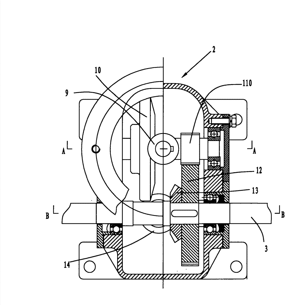
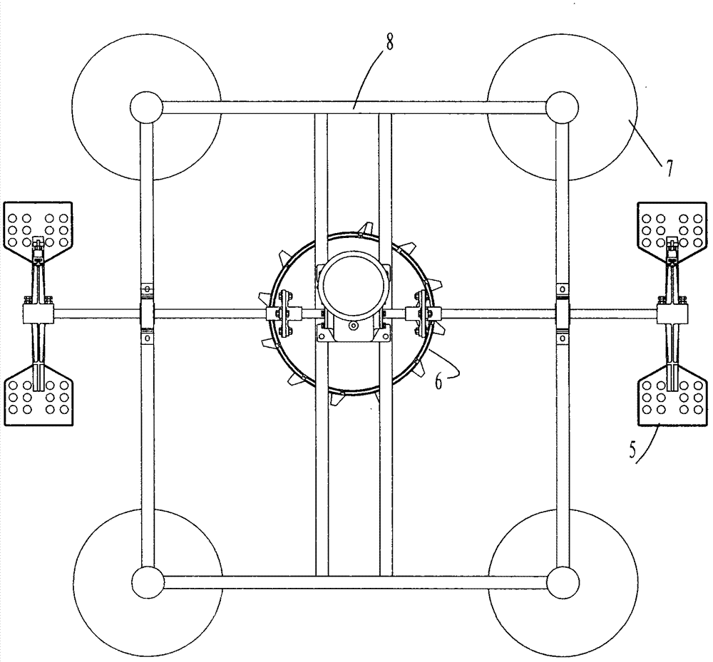
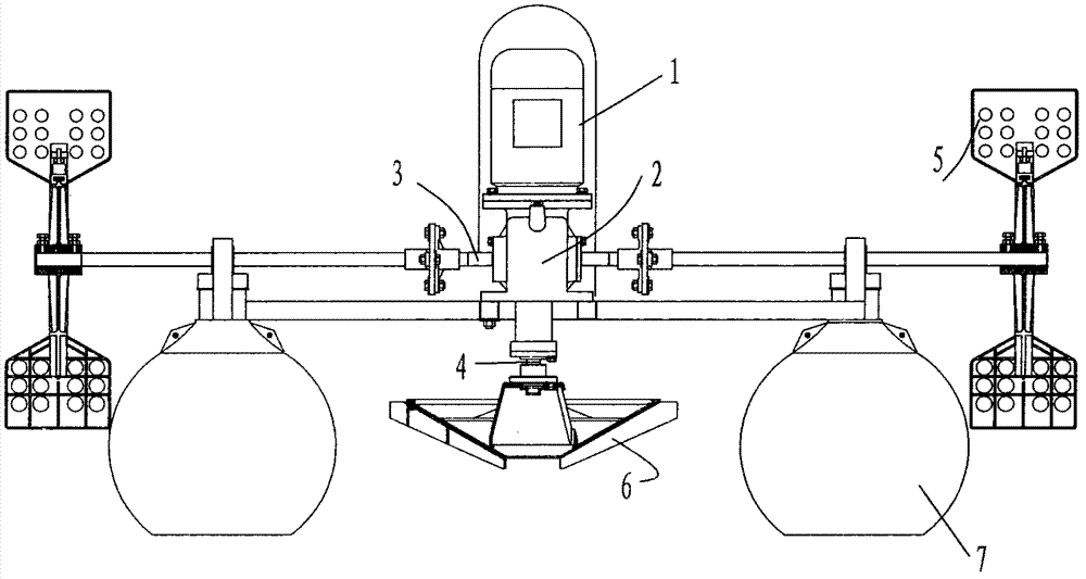
[0022] Embodiment 1, combining Figure 1 to Figure 2 , an aerator, including a motor 1, a speed reducer 2, a first output shaft 3, a second output shaft 4, a water wheel 5, an impeller 6, a floating body 7, and a frame 8.

[0023] See Figure 1-2 , The motor 1 and the reducer 2 are installed on the frame 8, and the frame 8 is installed on the floating body 7; the two ends of the first output shaft 3 are equipped with water wheels 5; the impeller 6 is installed on the lower end of the second output shaft 4.

[0024] See Figure 3-7 In the reducer 2, the power is transmitted to the first output shaft 3 and the second output shaft 4 in this way: the motor 1 is installed on the reducer 2, and the motor shaft head extends into the reducer and is equipped with the first driving bevel gear 9 , the first driving bevel gear 9 meshes with the first driven bevel gear 10, so that the gear shaft 11 connected with the first driven bevel gear 10 rotates, and the diameter of the first drive...

Embodiment 2

[0027] Example 2, see Figure 8 , the difference between embodiment 2 and embodiment 1 is that the form of the floating body 7 is different, and the form and function of other devices are the same, so it will not be described again.


PUM


Abstract

The invention relates to an aerator for use in an aquaculture industry, which comprises a motor, a speed reducer, a first output shaft, a second output shaft, water wheels, an impeller, a machine frame and a floating body, wherein the water wheels are installed at two ends of the first output shaft; the impeller is installed at an end part of the second output shaft; and the motor drives the first output shaft and the second output shaft to rotate towards different directions at the same time through the speed reducer so as to drive the water wheels and the impeller to rotate. The aerator hasthe advantage of reasonable structure and design; one speed reducer can drive the water wheels and the impeller to rotate at the same time, so that the depth aeration of a large-area water body is realized, and the aeration capacity and the aeration speed are greatly improved; moreover, the cultivation investment cost of aquatic breeding farmers is saved, and energy sources are saved.

Description

technical field [0001] The invention relates to an aerator for aquaculture industry. Background technique [0002] There are two commonly used aeration methods for existing aerators. The first is the waterwheel type aeration, and the second is the impeller type aeration. The waterwheel type has a large oxygenation area, and the impeller type can increase the water depth. oxygen. [0003] If the pond needs to increase oxygen in both the wide area and the depth, the water wheel type aerator and the impeller type aerator must be installed respectively, which greatly increases the cost of the aquaculture farmers and does not save energy. Contents of the invention [0004] Therefore, the object of the present invention is to provide an aerator that realizes simultaneous aeration in both depth and wide area by one machine. [0005] The purpose of the present invention is to realize like this: [0006] An aerator includes a motor, a speed reducer, a first output shaft, a secon...

Claims


Application Information

Patent Timeline
Patent Type & Authority Patents(China)
IPC IPC(8): A01K63/04C02F7/00
CPCY02W10/10
Inventor 冯德祥何志强
Owner 广东顺德凯雷机械有限公司
Learn More