
Method and device for improving HPRF (High-Pulse Repetition Frequency) performance in Doppler ultrasonic imaging

A Doppler ultrasound and imaging technology, which is applied in the field of pulse wave spectrum Doppler imaging, can solve the problems of not being optimal, reducing the signal-to-noise ratio of the target spectrum, and not being desirable, so as to improve the imaging effect and increase the signal-to-noise ratio Effect

Active Publication Date: 2011-07-27
SHENZHEN MINDRAY BIO MEDICAL ELECTRONICS CO LTD
View PDF5 Cites 6 Cited by
  • Summary
  • Abstract
  • Description
  • Claims
  • Application Information

AI Technical Summary

Problems solved by technology

[0007] The disadvantage of the existing HPRF technology is that the above-mentioned PRF is a preset fixed gear. In actual application, only a certain gear is selected by the user for transmission and reception, and the actual sampling gate position is based on the target blood vessel or tissue of the target patient. It is determined by the position, which is arbitrarily variable
In some real sampling gate positions, these PRFs may cause the time when the target signal arrives at the probe to be too close to the pulse emission time, thereby reducing the signal-to-noise ratio of the obtained target spectrum and affecting the user's judgment on the acquisition of target speed information
That is to say, for some arbitrarily selected positions of real sampling gates, these preset PRFs may not be optimal or even desirable

Method used


Image

  • Method and device for improving HPRF (High-Pulse Repetition Frequency) performance in Doppler ultrasonic imaging
  • Method and device for improving HPRF (High-Pulse Repetition Frequency) performance in Doppler ultrasonic imaging
  • Method and device for improving HPRF (High-Pulse Repetition Frequency) performance in Doppler ultrasonic imaging

Examples


Embodiment Construction

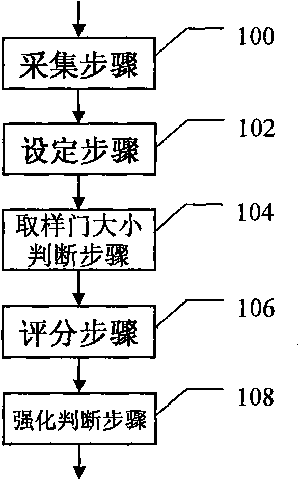
[0022] A method for improving HPRF performance in Doppler ultrasound imaging according to an embodiment of the present invention includes: an acquisition step 100 , a setting step 102 , and a scoring step 106 . In other embodiments, the sampling gate size judgment step 104 and / or the strengthening judgment step 108 are also optionally included, such as figure 1 shown. The steps are described in detail below.

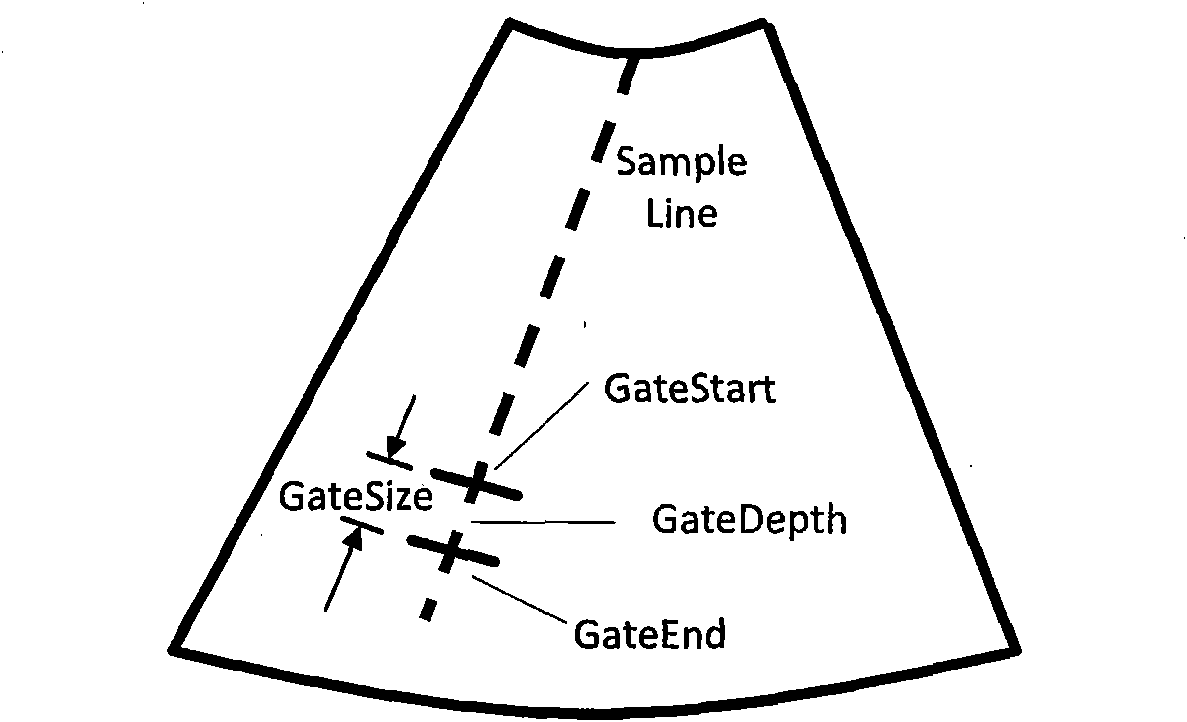
[0023] First, obtain the parameters selected by the user interface, including sampling gate position information and obtain the PRF gear selected by the user interface (step 100), wherein the sampling gate position information includes: sampling gate depth SVD, i.e. figure 2 GateDepth in, and the sampling gate size GateSize, such as figure 2 shown. The sampling gate here is the real sampling gate, and the corresponding sampling gate depth is the real sampling gate depth. In addition, the standard PRF value corresponding to the PRF gear selected through the user int...


PUM


Abstract

The invention discloses a method and a device for improving HPRF (High-Pulse Repetition Frequency) performance in Doppler ultrasonic imaging, wherein the method comprises the following steps of: an acquisition step for acquiring PRF gear selected by a user, the depth of a sampling door and the size of the sampling door by an interactive interface; a setting step for setting a selectable PRF range according to a standard PRF value corresponding to the selected PRF gear; and a scoring step for selecting the PRFs in sequence according to the preset step length in the selectable PRF range so as to carry out scoring, wherein the PRF with the largest score is taken as the optimum PRF of the selected gear and the optimum PRF is used for transmitting ultrasonic pulse. According to the method and the device disclosed by the embodiment of the invention, the optimum PRF is calculated in real time according to the PRF gear selected by the user and the position of the sampling door so as to carry out transmission, and the signal-to-noise ratio of a Doppler frequency spectrogram obtained under HPRF can be improved, so that the imaging effect of Doppler frequency spectrum can be improved.

Description

technical field [0001] The invention relates to pulse wave spectrum Doppler imaging, in particular to a method and device for improving HPRF performance in Doppler ultrasound imaging. Background technique [0002] In the Pulsed Wave Spectral Doppler Imaging (PW imaging) process of the medical ultrasound imaging system, the ultrasound front-end transmits ultrasound pulse signals into the target tissue of the human body at regular intervals to detect its Doppler frequency shift ( Doppler Frequency Shift) information. In traditional PW imaging, in order to realize the target positioning function, that is, to ensure that the obtained velocity information does come from the target position (that is, the sampling gate depth (Sample Volume Depth, SVD)), the time interval of pulse repetition (Pulse Repeat Interval, PRI) will be limited by the depth of the target position, that is, the time interval PRI between two adjacent pulses must be greater than the time for the ultrasonic wav...

Claims


Application Information

Patent Timeline
IPC IPC(8): A61B8/00
CPCA61B8/467G01S7/5205A61B8/488G01S15/8986G01S7/52019
Inventor 李双双李雷
Owner SHENZHEN MINDRAY BIO MEDICAL ELECTRONICS CO LTD
Learn More