Microwave catalytic reactor system

A microwave reactor and microwave catalysis technology, applied in the chemical/physical/physical-chemical process of applying energy, etc., can solve the problems of low processing efficiency, inability to continuously adjust, and the inability of continuous operation of reaction materials to achieve structural science. reasonable effect

Inactive Publication Date: 2011-07-27
XIANGTAN UNIV
View PDF6 Cites 22 Cited by
  • Summary
  • Abstract
  • Description
  • Claims
  • Application Information

AI Technical Summary

Problems solved by technology

Its disadvantages: it can only treat waste water, and the treatment efficiency is not high
These modifications to the oven cavity can certainly solve some problems, but there are still many inconveniences in this modified household microwave oven: (1) the output power is set b...

Method used


Image

  • Microwave catalytic reactor system
  • Microwave catalytic reactor system

Examples


Embodiment 1

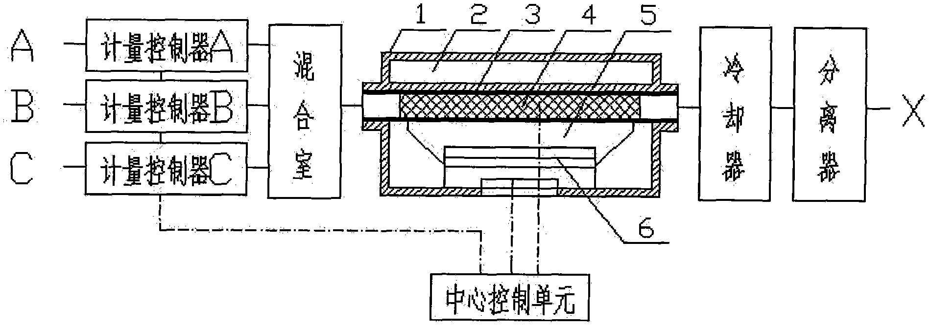
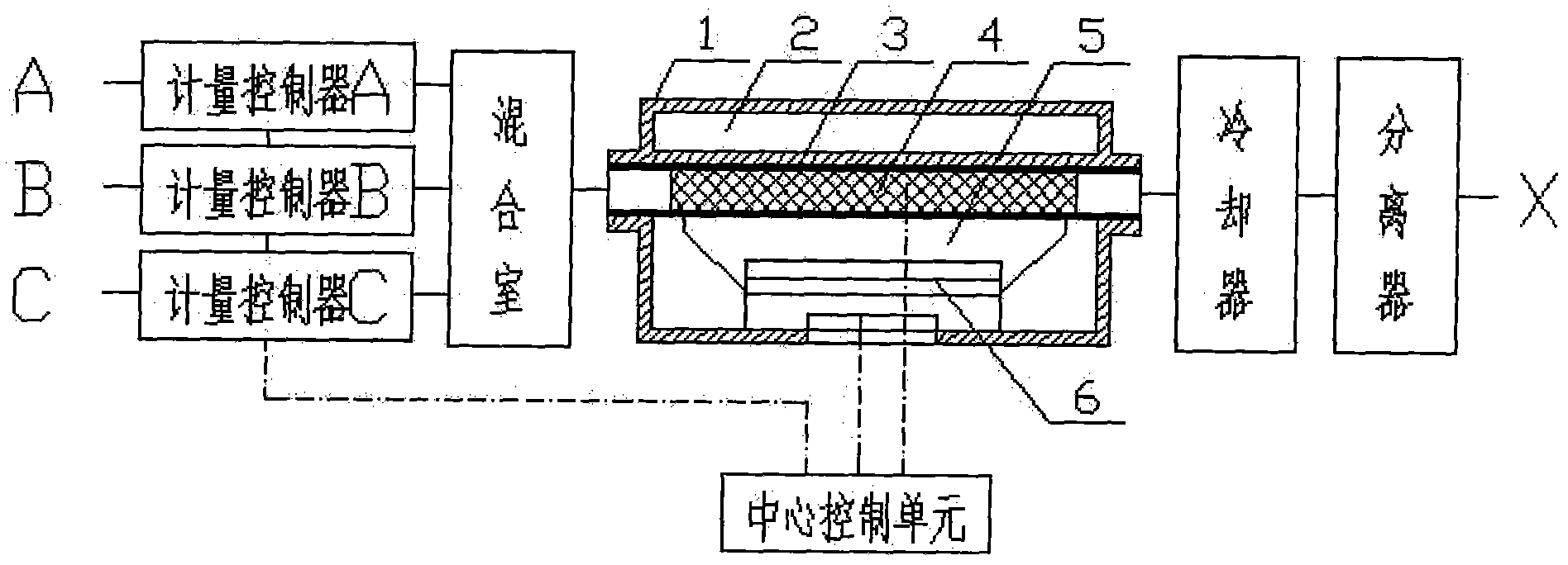
[0024] A feed port A is directly connected to the microwave reactor, and then discharged through the discharge port X. A reaction tube 3 and a microwave resonance cavity 5 are installed in the reactor body 1 of the microwave reactor; a microwave tube 6 is installed in the microwave resonance cavity 5; a catalyst 4 is filled in the reaction tube 3; and a catalyst 4 is installed Temperature sensor; the control circuit and temperature sensor of the microwave tube 6 are electrically connected to the central control unit. A forced-circulating cooling water chamber 2 is arranged between the outer wall of the reaction tube 3 and the reactor body 1, a water tank for forcedly circulating cooling water is installed outdoors, and the cooling water chamber 2 is connected to the water tank through a pipe and a water pump.

Embodiment 2

[0026] On the basis of Example 1, a metering controller is added between the feed port A and the microwave reactor, and the others are the same as in Example 1. The control circuit of the added metering controller is also electrically connected with the central control unit.

Embodiment 3

[0028] On the basis of Example 2, the feed port is A, B or the feed port is A, B, C or more. In this embodiment, the three feed ports are A, B, C, and the matching metering controller There are also three metering controllers A, metering controller B, and metering controller C. The mixing chamber is added before the microwave reactor. The others are the same as in Example 2. The control circuit of the added metering controller is also electrically connected with the central control unit.

[0029] The above embodiments 1-3 are used to treat waste gas or wastewater. Such as:

[0030] Catalyst 4 is 5ml of activated carbon.

[0031] Standard NO gas enters from the feed port A, oxygen enters from the feed port B, and mixes through the mixing chamber. The NO gas flow rate is 160ml / min, and the space velocity is 1920h -1 ; The intake NO content is 1000ppm, the oxygen content is 5.88%, the microwave power selects automatic gear control, and the temperature of the microwave catalytic react...


PUM


Abstract

The invention relates to a microwave catalytic reactor system comprising a feeding hole, a measuring controller, a mixing chamber, a microwave reactor and a discharging hole which are sequentially connected, wherein a reaction tube (3) and a microwave cavity (5) are installed in a reactor body (1) of the microwave reactor; a microwave tube (6) is installed in the microwave cavity (5); a catalyst (4) with a microwave absorption characteristic is filled in the reaction tube (3); a temperature sensor is arranged in the catalyst (4); and the measuring controller, a control circuit of the microwave tube (6) and the temperature sensor are electrically connected with a central control unit. A forced circulation cooling water chamber (2) is arranged between the outer wall of the reaction tube (3) and the reactor body (1), a water tank for holding forced circulation cooling water is installed outdoors, and the cooling water chamber (2) and the water tank are connected with a water pump through pipelines. An outlet of the microwave reactor can be selectively connected with a cooler and a separator. The microwave catalytic reactor system can be used for continuous flowing air (liquid) and solid catalytic reaction, and can be used for treating waste water, waste gas and the like.

Description

Technical field [0001] The invention relates to the technical field of microwave catalysis, in particular to a multifunctional microwave catalysis reactor device system. Background technique [0002] In chemical reactions, microwaves can directly interact with chemical systems to promote various chemical reactions. Microwave action not only has a "thermal effect", but also a special "non-thermal effect". Since the Harwell laboratory used microwave technology to successfully treat nuclear waste, microwave technology has been widely used in organic chemistry, inorganic material chemistry, analytical chemistry and other disciplines, and has gradually opened up a new field of microwave chemistry. A large number of documents have reported the application of microwave technology in chemical reactions, so the research in this field is currently a hot spot. In recent years, many researchers have tried to apply microwave heating to heterogeneous catalytic reaction processes, and the app...

Claims


Application Information

Patent Timeline
IPC IPC(8): B01J19/12
Inventor 周继承阳鹏飞王哲
Owner XIANGTAN UNIV
Why Eureka
Try Eureka