Integrated oxidation ditch

An oxidation ditch and pond body technology, applied in the field of integrated oxidation ditch, can solve the problems of large area occupied by the sedimentation area, limited actual land saving area, and increased land occupation of the oxidation ditch, so as to increase the area of ​​the sedimentation area and save the occupied area. The effect of reducing the floor area and operating energy consumption

Active Publication Date: 2011-07-27
JIANGSU YIHUAN GROUP +2
View PDF10 Cites 14 Cited by
  • Summary
  • Abstract
  • Description
  • Claims
  • Application Information

AI Technical Summary

Problems solved by technology

However, high sludge concentration will inevitably increase the concentration of suspended sludge in the ditch, and the high concentration of suspended sludge in the ditch makes the separation of mud and water can only be designed according to the lower surface load, resulting in a larger area of ​​the sedimentation area, thus The area occupied by the oxidation ditch is increased, and the area saved by using the deep ditch may be offset by the increase in the

Method used


Image

  • Integrated oxidation ditch
  • Integrated oxidation ditch
  • Integrated oxidation ditch

Examples


Embodiment 1

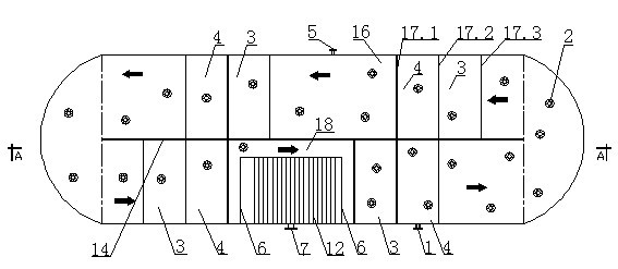
[0024] Embodiment 1: see figure 1 , 2 , The integrated oxidation ditch of the present invention is separated by a partition wall 14 to separate parallel symmetrical double ditch, with semicircular connections at both ends to form a circulating oxidation ditch. There are several groups in the single ditch, and each group is separated by interlaced partitions 17.1, 17.2 and 17.3 to form an upflow zone 3 and a downflow zone 4, followed by a biochemical zone 16, forming an oxidation ditch A 2 / O process, adding commercially available hollow wheel-shaped short tube suspension filler 2 accounting for 20% of the ditch volume in the oxidation ditch. A tubular microporous aerator 8 is installed at the bottom of the upflow zone 3, and a settling zone 12 separated by a partition wall 6 is built at the end of the oxidation ditch treatment process. The width of the settling zone accounts for 2 / 3 of the width of the oxidation ditch, leaving a circulation passage 18. There are asymmetric h...

Embodiment 2

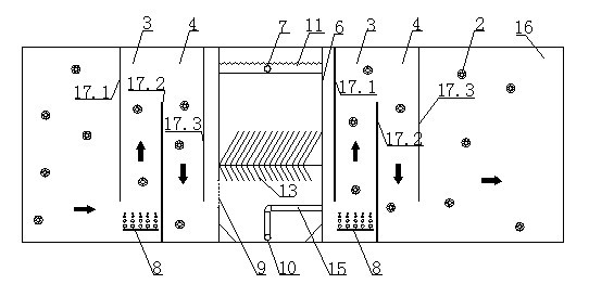
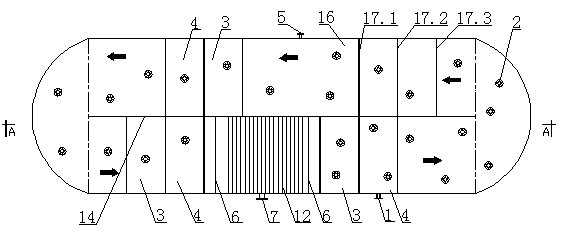
[0026] Example 2: see image 3 , 4 , as in Example 1, wherein the settling zone 12 is set at the same width as the oxidation ditch, the bottom of the settling zone is suspended, and a circulation flow channel 19 is reserved between the bottom of the settling zone, and the sedimentation and separation sludge can be discharged through the bottom mesh plate 20 and return with the circulating flow. The valve-controlled sludge discharge pipe 10 is set at the bottom of the sedimentation zone. The return flow and sludge discharge volume of sedimentation and separation sludge are controlled and distributed by 10 valves at the sludge discharge port according to the process requirements.

Embodiment 3

[0027] Embodiment 3: see Figure 5 , as embodiment 2 (also can be as example 1), below the upflow zone, downflow zone, and biochemical zone (the middle and lower part of the oxidation ditch) there is a partition plate 21 to separate the upper and lower layers, and the aeration device 8 is arranged at the bottom of the upper floor. 22 below the partition 21 is an anoxic zone, 23 behind the flow of the treatment liquid is an anaerobic zone, and 24 is an aerobic biochemical zone.


PUM


Abstract

The invention relates to an improved integrated oxidation ditch, which comprises an oxidation ditch body, an aeration device at the bottom or the lower middle part and a built-in partition precipitation zone at the tail end of a treatment flow. The integrated oxidation ditch is characterized in that: a suspended filler is filled in the oxidation ditch body, a filler intercepting net is arranged at the water inlet of at least the precipitation zone, and a transverse herringbone folded plate or a bent pipe mud-water separation filler is arranged in the precipitation zone. The quantity of microbes in the oxidation ditch is increased, the treatment volume load is improved, the increased biomass is mainly centralized on the suspended filler, the actual suspended sludge concentration in the water of the oxidation ditch is not increased or reduced and can be controlled to be less than 3,000mg/l, the built-in partition precipitation zone can be designed according to the high load, the biomass is increased, the area of the precipitation zone is not increased or properly reduced, the occupation area of the oxidation ditch is actually and effectively saved, the occupation is saved by 1/3 to 1/5 compared with a common deep oxidation ditch and by 10 to 20 percent compared with a deep oxidation ditch with a precipitation zone, the suspended biological filler can save the running energy consumption and the running energy consumption can be reduced by 20 to 30 percent.

Description

technical field [0001] The invention is an improvement to the integrated oxidation ditch, and particularly relates to an integrated oxidation ditch with high biomass, less suspended sludge in water, small built-in sedimentation area, bottom aeration and deep ditch type integrated oxidation ditch. Background technique [0002] As an innovation of the activated sludge process, the oxidation ditch process has the characteristics of simple process flow, convenient operation and management, stable treatment effect, and good effluent quality compared with the traditional activated sludge process. It is a mature method that is widely used in sewage treatment. Water treatment technology occupies a very high application proportion in water treatment. Oxidation channels usually use surface aeration devices such as rotary discs, rotary brushes, surface aerators, etc., to simultaneously supply oxygen to the water and push flow circulation. However, since the mixed mud water circulation ...

Claims


Application Information

Patent Timeline
IPC IPC(8): C02F3/12C02F9/14
CPCY02W10/10
Inventor 杨超杭品艳杭明辉刘滨张宇
Owner JIANGSU YIHUAN GROUP
Why Eureka
Try Eureka