
Motorized high-speed hydraulic compacting machine

A mobile, tamping machine technology, applied in soil protection, construction, infrastructure engineering, etc., can solve the problems of reducing the impact force of the target foundation, frequent oil leakage of hydraulic cylinders, poor tamping effect, etc., to reduce production and construction costs , energy saving, high energy efficiency

Inactive Publication Date: 2012-05-02
BEIJING HUANQIU HUABANG TRAFFIC TECH DEV
View PDF2 Cites 0 Cited by
  • Summary
  • Abstract
  • Description
  • Claims
  • Application Information

AI Technical Summary

Problems solved by technology

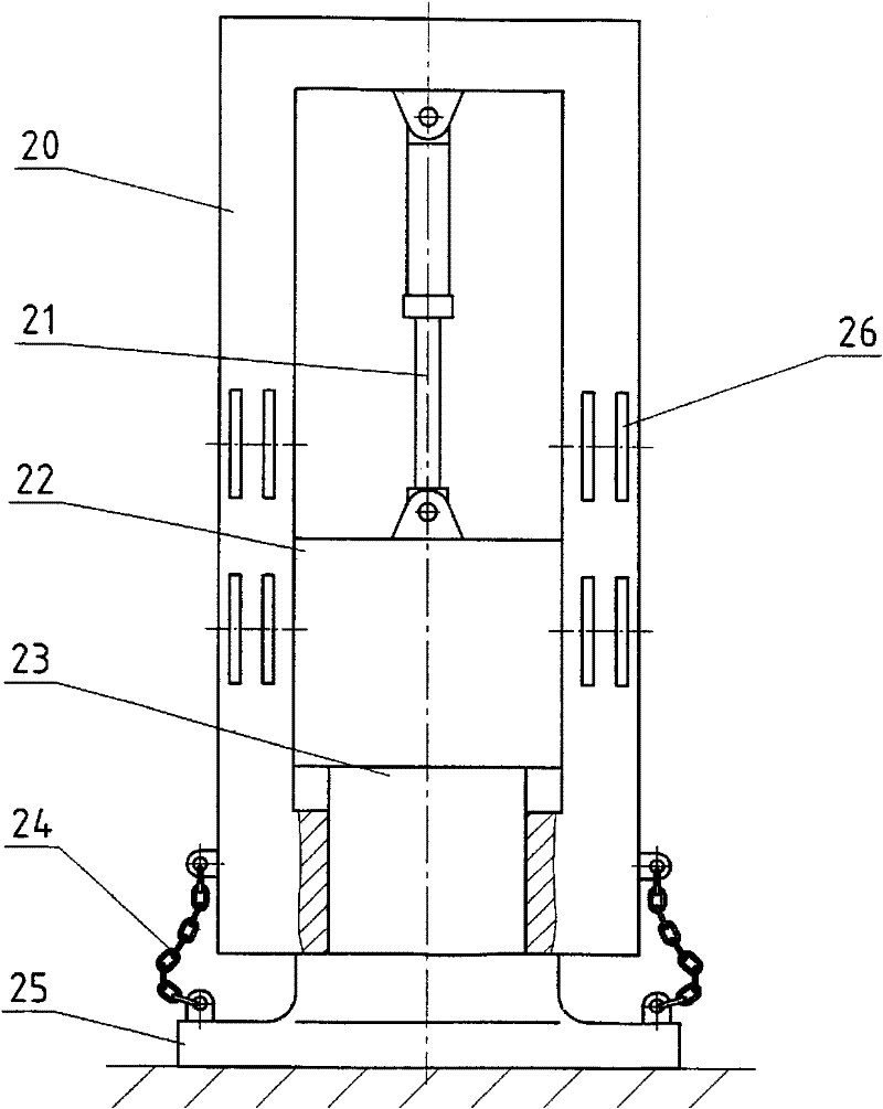
However, there are the following problems in this prior art impact rammer: the lifting mechanism 21 is usually a hydraulic cylinder, because the upper hydraulic cylinder of this impact rammer and the rammer 22 are connected by a pin shaft, which is a hard connection, so when the rammer After the hammer 22 impacts the ram head 23 and the ram plate 25 at high speed, the rebound force generated by the foundation will directly act on the hydraulic cylinder, resulting in frequent oil leakage of the hydraulic cylinder and low efficiency, and this problem is very difficult to solve
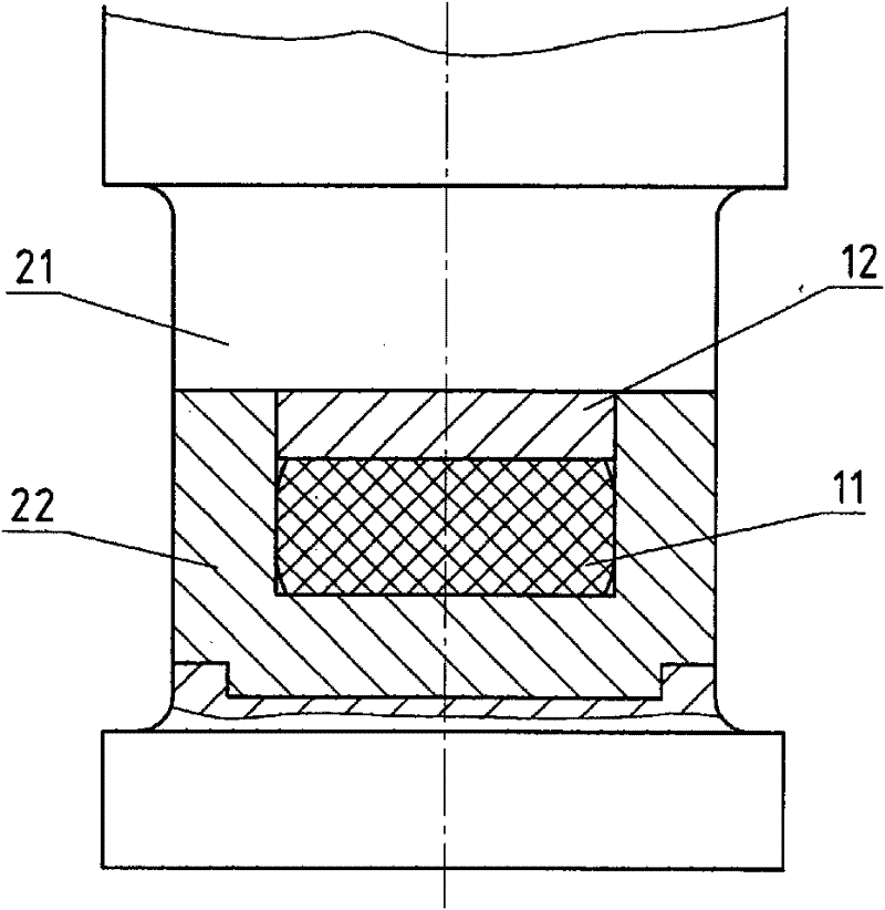
But there are following problems in the impact rammer buffer device of this prior art: although the rebound force of the foundation to the hydraulic oil cylinder can be alleviated after the buffer is added, the impact force to the target foundation is greatly reduced, so the compacting effect is poor and the energy waste is large , so this structure cannot fundamentally solve the contradiction between impact buffering and tamping force
The existing tamping machine rammers are all made of integral casting. Once cast, the weight will be determined accordingly, so it cannot be changed in actual construction.
However, as we all know, when the foundation is different, the tamping force required in the construction process will be different. When a large tamping force is not needed, a lot of energy will be wasted if a heavy tamping machine is used. The method of changing the model of the tamping machine to meet the tamping requirements, but in reality, the construction unit is often unwilling or unable to purchase the same equipment of many different models

Method used


Image

  • Motorized high-speed hydraulic compacting machine
  • Motorized high-speed hydraulic compacting machine
  • Motorized high-speed hydraulic compacting machine

Examples


Embodiment Construction

[0020] The motorized high-speed hydraulic compactor provided by the present invention will be described in detail below with reference to the accompanying drawings and specific embodiments.

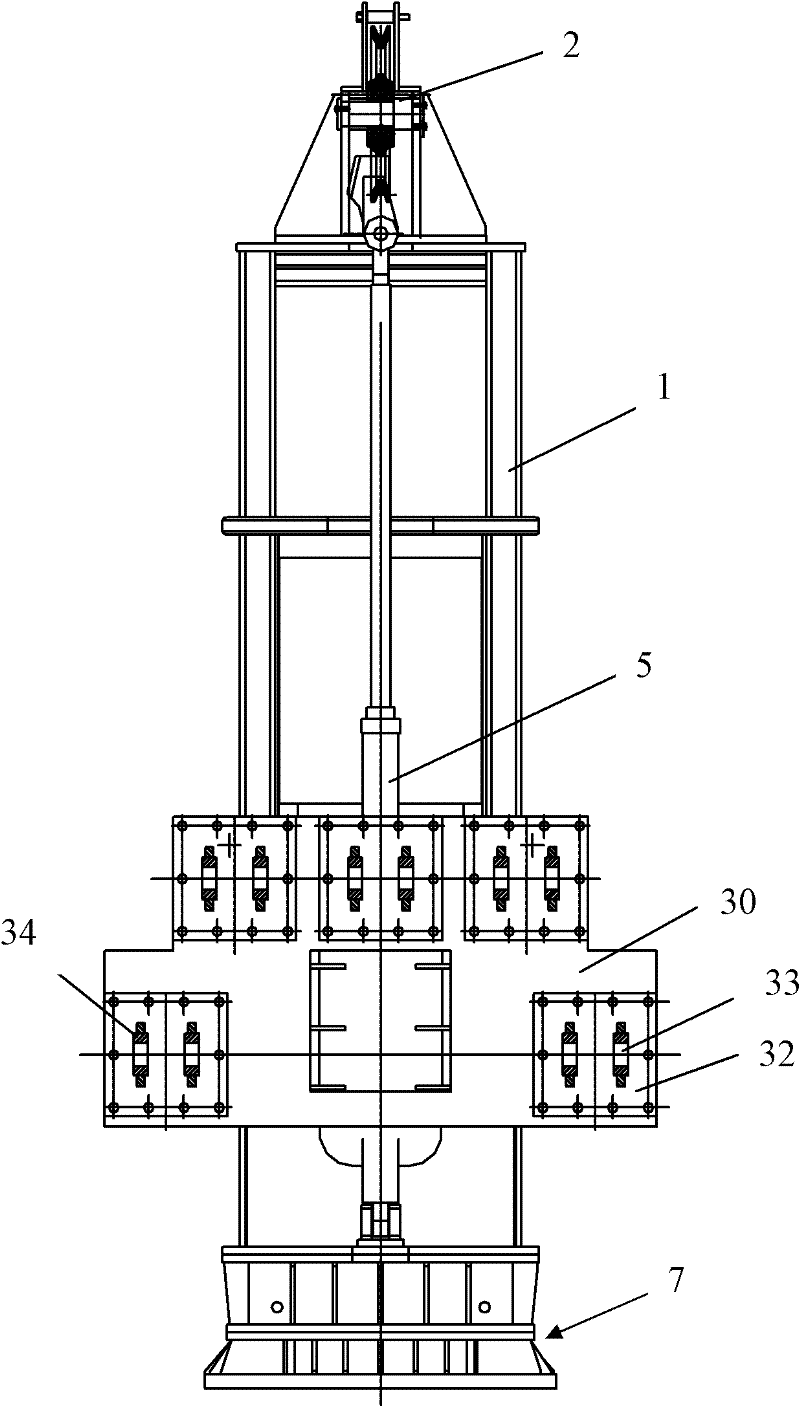
[0021] Such as Figure 3-Figure 8 As shown, the motorized high-speed hydraulic ramming machine provided by the present invention includes a ramming frame 1, a pulley device 2, a steel wire rope 3, a ramming hammer 4, a hydraulic cylinder 5, a transition seat 9, a tamping seat 7, a plurality of guard plates 8 and two long Pin shaft 51; wherein: the rammer frame 1 is a cube-shaped frame structure, used to support the rammer 4 and the hydraulic cylinder 5, and simultaneously serves as a guide device for the rammer 4; the pulley device 2 is installed on the top of the rammer frame 1; the rammer 4 is It is arranged in the ramming hole on the ram frame 1 in a way that can vertically reciprocate, and it is composed of an upper hammer body 14 and a lower hammer body 15 connected to each other, an...


PUM


Abstract

The invention relates to a motorized high-speed hydraulic compacting machine. The motorized high-speed hydraulic compacting machine comprises a compacting frame, a pulley device, a steel wire rope, a hammer ram, a hydraulic oil cylinder, a transition seat, a compacting seat, a plurality of protective plates and two long pin shafts. In the motorized high-speed hydraulic compacting machine, the oilcylinder is connected with the hammer ram through the flexible connection way, thereby fundamentally preventing rebounding force of a foundation from being directly acted on the hydraulic oil cylinder, further reducing the oil leakage problem of the hydraulic oil cylinder due to transfer of impact force and finally greatly prolonging the service life of the device. In addition, as the device doesnot need to use a cushion pad, the hammer ram is used for directly ramming a compacting plate and the compacting plate is further used for compacting the foundation, the compacting force can be completely used for compacting on the foundation, and the utilization rate of energy and the working efficiency are high.

Description

technical field [0001] The invention relates to a compacting machine, in particular to a motorized high-speed hydraulic compacting machine. Background technique [0002] Hydraulic high-speed compactor (also known as impact rammer) is a special compaction equipment used for compacting filling or soft ground, usually installed on excavators or loaders, and powered by the hydraulic system on the excavator or loader, with Good maneuverability, high efficiency and controllability, mainly including tamping frame, hydraulic cylinder, rammer and tamping plate and other devices. A kind of impact rammer is just disclosed in No. 02270354.3 of Chinese Utility Model Patent. figure 1 It is a schematic diagram of the forward structure of the impact rammer in this prior art. Such as figure 1 As shown, this prior art impact rammer includes a ram frame 20, a ram hammer 22, a ram head 23, a ram plate 25, a chain 24 and a lifting mechanism 21; wherein the ram hammer 22 is installed in the ra...

Claims


Application Information

Patent Timeline
Patent Type & Authority Patents(China)
IPC IPC(8): E02D3/046
Inventor 曹立伟崔国敏刘锋谭加农贺杰
Owner BEIJING HUANQIU HUABANG TRAFFIC TECH DEV
Learn More