
Aluminum alloy sheet for battery cover and its production method

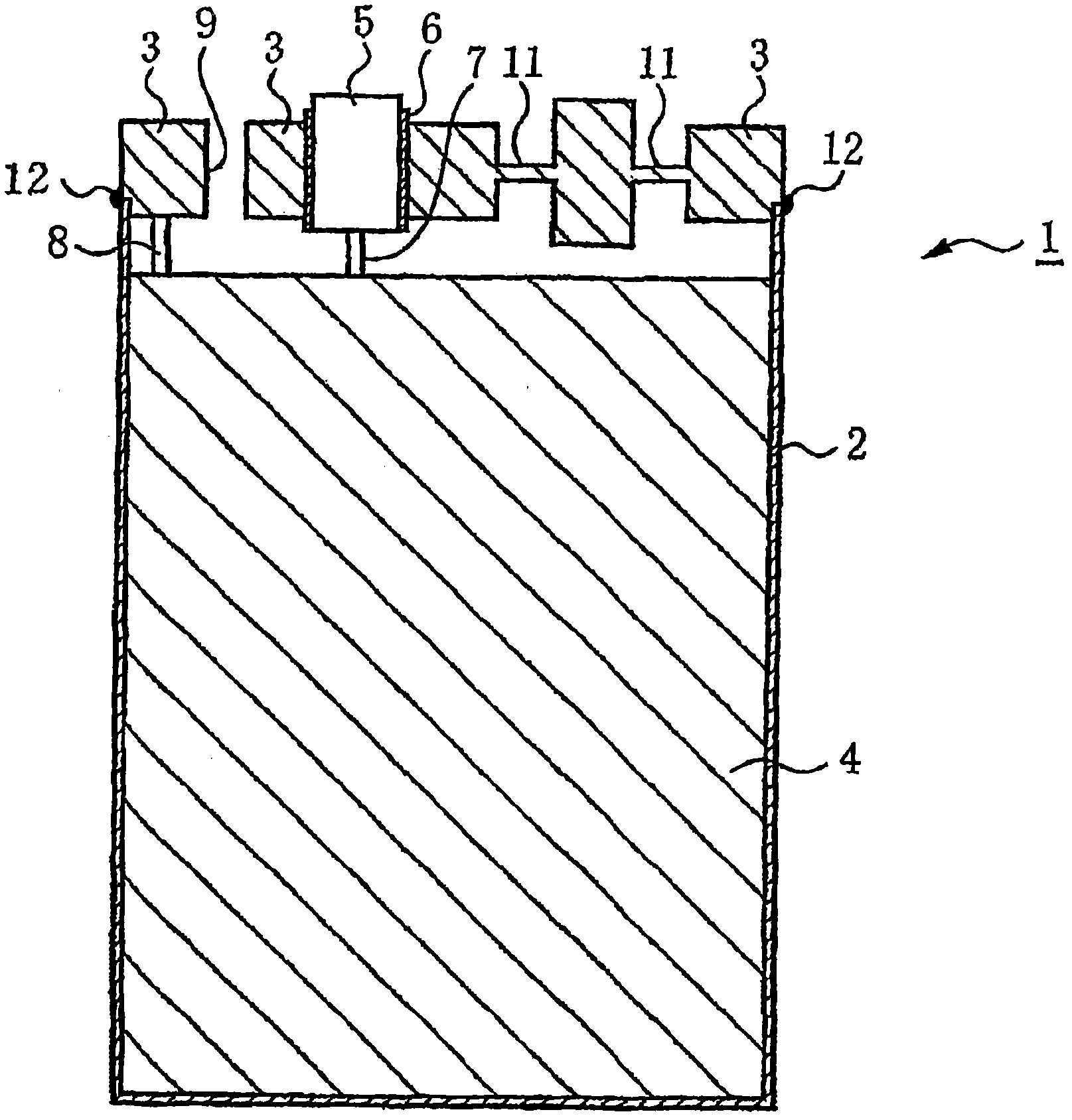
A technology of aluminum alloy plate and manufacturing method, which is applied in the direction of battery cover/end cover, metal rolling, battery pack parts, etc., can solve the problems of increased manufacturing process and deteriorated operability, and achieves excellent stamping formability, shrinkage and durability The effect of non-uniform compressive strength

Active Publication Date: 2011-07-27
NIPPON LIGHT METAL CO LTD
View PDF8 Cites 9 Cited by
  • Summary
  • Abstract
  • Description
  • Claims
  • Application Information

AI Technical Summary

Problems solved by technology

[0010] However, in the solution proposed in Patent Document 3, the following problems arise: Since the process of covering the metal sheet as the explosion-proof part requires another route, the manufacturing process increases, and although it is not necessary to inspect the thickness of the metal sheet But the proper degree of closeness must be checked by other means
That is, in the manufacture of the entire battery, there is a problem that operability deteriorates due to an increase in the number of manufacturing steps.

Method used


Image

  • Aluminum alloy sheet for battery cover and its production method
  • Aluminum alloy sheet for battery cover and its production method
  • Aluminum alloy sheet for battery cover and its production method

Examples


Embodiment 1

[0064] Next, specific examples will be described.

[0065] smelting as figure 1 An aluminum alloy molten metal having the composition shown above was cast into an ingot by a semi-continuous casting method with a thickness of 530 mm, a width of 1100 mm, cooling water from a mold of 3.0 liters / cm min, and an ingot withdrawal speed of 50 mm / min.

[0066] Next, after end-cutting the ingot, it was subjected to a homogenization treatment at 600°C for 2 hours, and hot rolling was started after holding, and it became a hot-rolled sheet with a thickness of 6 mm at a finishing temperature of 400°C. Next, cold-rolled 4-pass (pass) becomes a 1.4-mm-thick cold-rolled sheet.

[0067] Thereafter, the cold-rolled sheets of alloy No. 1, 2, 3, and 5 were heated to 500°C at an average speed of 200°C / sec, and after being kept at this temperature for 10 seconds, they were heated at an average speed of 200°C / sec. The rate of rapid cooling to 200 ° C for annealing. Next, the above-mentioned annea...

Embodiment 2

[0083] The aluminum alloy having the composition of No. 2 in the above Table 1 was used as a test material, and as shown in Table 3, various changes were made to the homogenization treatment, the cold rolling ratio before the final annealing, and the final annealing conditions to obtain Annealed plate with a thickness of 1mm.

[0084] For each of the obtained annealed sheets, as in Example 1, the crystal grain width of the rolling surface was measured by the cross-section method, and at the same time, the compressive strength was measured by press forming to a thickness of 20 μm (the n number was 10). The measurement area was set to 2 mm×3 mm.

[0085] The results are shown in Table 4.

[0086] table 3

[0087] manufacturing conditions

[0088]


PUM

PropertyMeasurementUnit
thicknessaaaaaaaaaa
widthaaaaaaaaaa
thicknessaaaaaaaaaa

Abstract

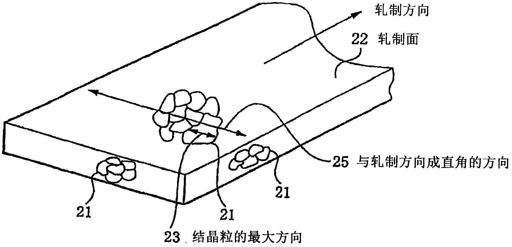
An aluminum alloy plate for a battery case and a manufacturing method thereof are provided to obtain desired internal pressure strength, reduce a deviation of internal pressure strength, and form a thin explosion-proof part accurately by forming the aluminum alloy plate with fine crystal grains. An aluminum alloy plate for a battery case(2) comprises Fe : 1.15 to 1.35 weight%, Mn : 0.40 to 0.60 weight%, the remainder Al, and unavoidable impurities. The aluminum alloy plate has a composition having, as the impurities, less than 0.05 weight% of Si, less than 0.05 weight% of Mg, and less than 0.05 weight% of Mg. The aluminum alloy plate has a structure in which a maximum width of a crystal grain is less than 100 microns and an average of a width of the crystal grain is less than 25 microns with regard to a direction perpendicular to the rolling direction. Ti : 0.005 to 0.15 weight% and B : 0.0005 to 0.05 weight% are contained.

Description

[0001] This case is a divisional application of a patent application with an application date of December 29, 2007, an application number of 200710300846.7, and an invention title of "Aluminum alloy plate for battery cover and its manufacturing method". technical field [0002] The present invention relates to an aluminum alloy plate used for a battery cover, an aluminum alloy plate capable of producing a battery cover capable of exhibiting required compressive strength without annealing after forming the cover by press working, and a method for producing the same. Background technique [0003] Among batteries used in mobile devices such as mobile phones, from the viewpoint of weight reduction, rechargeable and dischargeable sealed batteries in which an electrolytic substance is accommodated in a case made of aluminum or an aluminum alloy are often used. [0004] However, in such rechargeable and dischargeable sealed batteries, in the past, when the battery is overcharged or ...

Claims


Application Information

Patent Timeline
Patent Type & Authority Applications(China)
IPC IPC(8): H01M2/04C22C21/00H01M50/159
CPCY02E60/12Y02E60/10C22C21/00B21B1/02B21B2001/225B21B2001/221H01M50/119H01M50/147
Inventor 藤井孝典高桥照荣石井秀彦
Owner NIPPON LIGHT METAL CO LTD
Learn More