Heat exchanger and method of manufacturing same

A technology of heat exchanger and manufacturing method, which is applied in the direction of heat exchange equipment, heat transfer modification, electric solid devices, etc., can solve the problems that the cooling performance cannot be improved, and the heat of the heating element is difficult to dissipate, so as to achieve mass production, structure and Simple processing and improved cooling performance

Inactive Publication Date: 2011-07-27
TOYOTA JIDOSHA KK
View PDF1 Cites 8 Cited by
  • Summary
  • Abstract
  • Description
  • Claims
  • Application Information

AI Technical Summary

Problems solved by technology

Therefore, the flow becomes faster at the central part of the flow path, while the flow becomes slower at the boundary layer in contact with the fins 111, and

Method used


Image

  • Heat exchanger and method of manufacturing same
  • Heat exchanger and method of manufacturing same
  • Heat exchanger and method of manufacturing same

Examples


Embodiment Construction

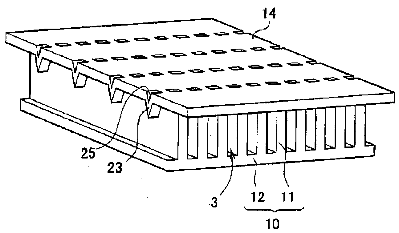
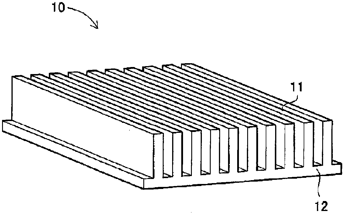
[0055] Next, one embodiment of the heat exchanger and its manufacturing method in the present invention will be described below with reference to the drawings. figure 1 It is a perspective view which shows the heat exchanger of this embodiment.

[0056] In this heat exchanger 1 , a plurality of fins 11 are arranged in a cylindrical body 2 to form a plurality of flow paths 3 communicating from an inlet opening 21 of the body 2 to an opposite outlet opening. The main body 2 of the heat exchanger 1 allows coolant to flow in, for example, a direction indicated by an arrow Q, and communicates from the inflow-side opening 21 to the opposite discharge-side opening.

[0057] in addition, figure 1 shows the heat exchanger 1 in which the inflow-side opening 21 and the discharge-side opening on the opposite side are largely opened on the main body 2, but in use, they are respectively closed and supplied with coolant not shown in the figure. pipe or coolant drain connection. Also, a ...


PUM


Abstract

Provided are a heat exchanger having a novel structure and efficiently cooling a heat generating body, and a method of manufacturing the heat exchanger. The heat exchanger (1) has flow paths (3) formed by being closed by an upper plate (14) and a lower plate (12) which have rectilinearly formed upstanding fins (11) parallelly arranged at specific intervals, and gaps extend between adjacent fins (11) in the top-bottom direction along the direction in which the fins (11) extend. Either of or both the upper plate (14) and the lower plate (12) are provided with projections (23) arranged in the longitudinal direction of the flow path (3) and projecting inward of the flow path (3).

Description

technical field [0001] The present invention relates to a heat exchanger in which a flow path is formed by a plurality of linear fins arranged in parallel, and the heat from a heating element is dissipated by passing a coolant through the flow path, and particularly relates to a flow of coolant capable of improving heat dissipation effect. A flow path heat exchanger and a manufacturing method thereof. Background technique [0002] In a hybrid car or the like, a semiconductor element is used in an inverter for driving a motor, and a water-cooled heat exchanger is used to cool the semiconductor element. Inverters equipped with semiconductor elements are required to have higher output, and at the same time, the demand for miniaturization and weight reduction is becoming stricter, so heat exchangers with excellent heat dissipation effects are required. Patent Document 1 below discloses a conventional heat exchanger with improved cooling performance. Figure 16 is a cross-sectio...

Claims


Application Information

Patent Timeline
IPC IPC(8): H01L23/473B21D22/02B21D53/04F28F13/12F28F13/08
CPCF28F13/06H01L23/473F28F3/12B21D53/04F28F3/02H01L2924/0002H01L2924/00
Inventor 森野正裕竹纲靖治井下宽史松井启仁
Owner TOYOTA JIDOSHA KK
Why Eureka
Try Eureka