High-temperature pulse flow yarn dyeing machine with ultra low bath ratio and control method thereof

A control method and ultra-low bath technology, applied in the direction of final product manufacturing, textile processing machine accessories, sustainable manufacturing/processing, etc., can solve problems such as time-consuming 3-4 times, large pollution, environmental pollution, etc.

Inactive Publication Date: 2011-08-03
高勋绿色智能装备(广州)有限公司
View PDF5 Cites 7 Cited by
  • Summary
  • Abstract
  • Description
  • Claims
  • Application Information

AI Technical Summary

Problems solved by technology

[0003] At present, the domestic dyeing and finishing equipment has the following problems: (1) The efficiency of dyeing and finishing equipment is low and the process time is long. The traditional overflow dyeing machine takes about 8-10 hours to dye a vat of cloth, and the dyeing cycle is long and time-consuming. Dyeing and finishing equipment made abroad takes 3 to 4 hours
(2) The pollution is large, and each cylinder dyeing requires a large amount of dye auxiliaries
(3) The water consumption is large. The water consumption per kilogram of fabric of the t...

Method used


Image

  • High-temperature pulse flow yarn dyeing machine with ultra low bath ratio and control method thereof
  • High-temperature pulse flow yarn dyeing machine with ultra low bath ratio and control method thereof
  • High-temperature pulse flow yarn dyeing machine with ultra low bath ratio and control method thereof

Examples


Embodiment 1

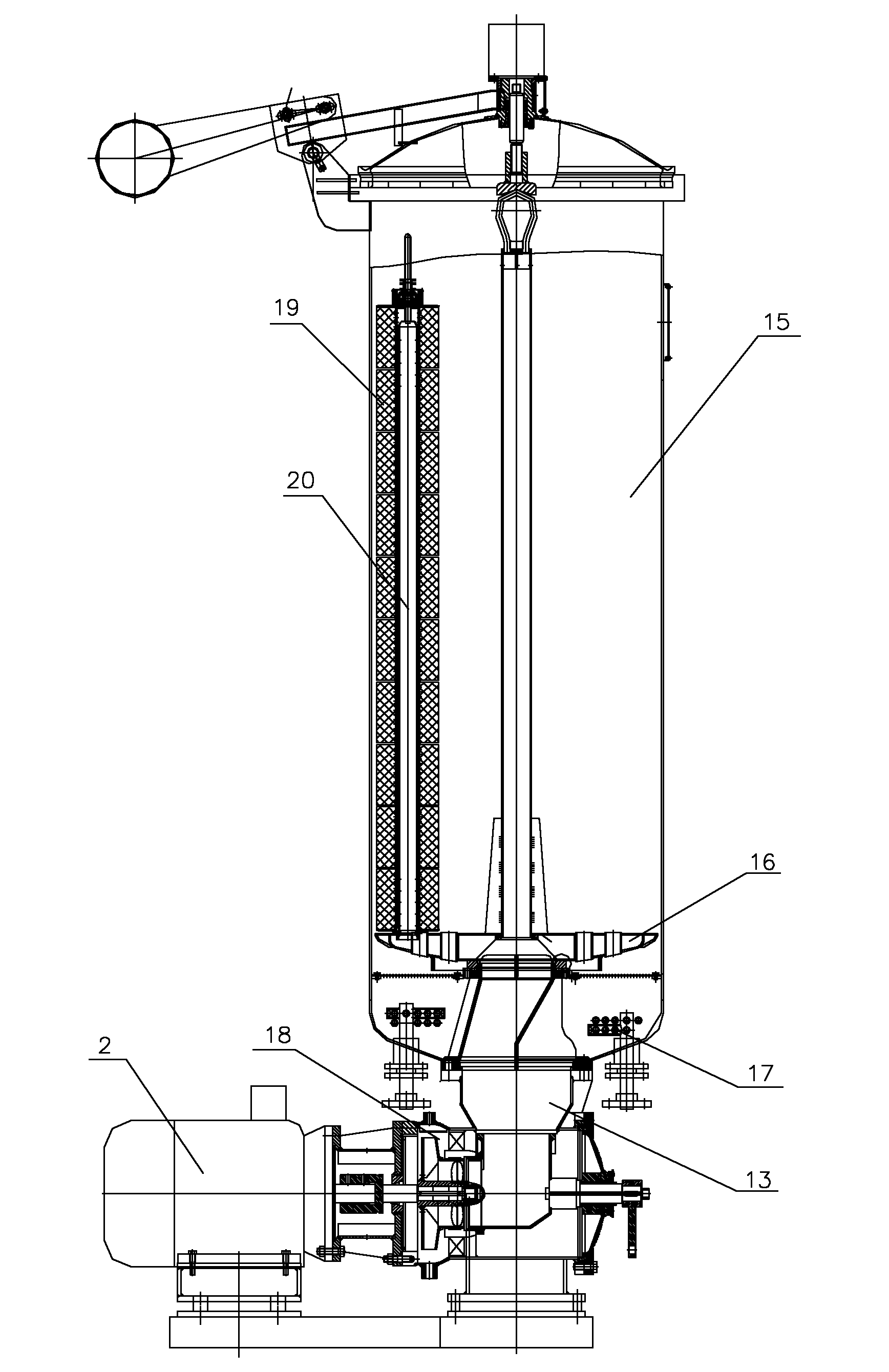
[0114] The main view of "high temperature yarn dyeing machine" is as follows: figure 1 As shown, the yarn dyeing machine consists of the following components:

[0115] (1) The basic configuration includes: main cylinder body, cylinder head, cylinder head counterweight, creel axis, creel disc, spindle, yarn lifting device, cylinder washing device, frequency conversion motor, gas filter, high temperature discharge mixed flow device , Soda mixer.

[0116] (2) Pumps and valves: axial flow vane, centrifugal pump vane, main circulation pump, guide vane, guide housing, volume sensor water inlet valve, high temperature discharge cooling valve, high temperature mixed flow discharge valve, master cylinder drain valve 2, Master vat drain valve 1, master vat steam inlet valve, master vat water inlet valve 2, master vat water inlet valve 1.

[0117] (3) Instrument sensors: thermometers, temperature probes, water level measuring devices, zero pressure switches, double needle pressure gaug...


PUM


Abstract

The invention discloses a high-temperature pulse flow yarn dyeing machine with an ultra low bath ratio and a control method thereof. The yarn dyeing machine comprises a dye vat, a creel, a heat exchange coiler, an adaptive water level monitoring device, a variable frequency motor, a three-level vane pump with an ultra low bath ratio and a dyeing computer. The method comprises the following steps: a time pulse generator in the dyeing computer gives out pulse flow data to a variable frequency motor controller to control the revolving rate of the variable frequency motor according to the set technological process; the variable frequency motor drives the three-level vane pump with an ultra low bath ratio to output dyeing flow in pulse flow type fluctuation; the output dyeing flow carries out adaptive adjustment according to an ideal reference model in the dyeing computer; the adaptive water level monitoring device gives out water-level reference identification information; and according to the information, a water level regulator and the variable frequency motor controller respectively regulate the water level and the variable frequency motor to reach the water level and the pulse flow required by the set technological process. The pulse flow dyeing technology in the invention conforms to the requirement of the minimum consumption of four factors, namely, water, energy, accessory ingredient and time for economical dyeing of ecological environment protection.

Description

technical field [0001] The invention relates to the field of yarn dyeing machine devices and process control, in particular to an ultra-low liquor ratio high temperature pulse flow yarn dyeing machine and a control method thereof. Background technique [0002] Package dyeing is the most widely used method in the yarn dyeing industry today. However, the bath of the conventional cheese dyeing machine is relatively large, and the dyeing cycle (especially the cotton yarn dyeing cycle) is long, and the time for heating, cooling, bleaching and washing accounts for more than half of the entire dyeing cycle, and consumes most of the dyeing cycle. water and electricity. In addition, the traditional method of unloading cheese from cheese dyeing machines is time-consuming and labor-intensive. Therefore, efforts should be made to develop short-process and environmentally friendly yarn dyeing technology. [0003] At present, the domestic dyeing and finishing equipment has the followin...

Claims


Application Information

Patent Timeline
IPC IPC(8): D06B3/09D06B5/00D06B23/00D06B23/20D06B23/24
CPCY02P70/62
Inventor 黎嘉球钟汉如罗湘春
Owner 高勋绿色智能装备(广州)有限公司
Why Eureka
Try Eureka