
Fuel heater system including hot and warm water sources

一种燃料加热、燃料的技术,应用在涡轮/推进装置的燃料加热、涡轮/推进燃料输送系统、装料系统等方向,能够解决燃烧器损坏、发动机操作降级、发动机性能低效等问题

Active Publication Date: 2011-08-03
GENERAL ELECTRIC TECH GMBH
View PDF5 Cites 10 Cited by
  • Summary
  • Abstract
  • Description
  • Claims
  • Application Information

AI Technical Summary

Problems solved by technology

[0006] However, given the limitations of conventional systems, different fuels of differing composition and calorific value may be sequentially delivered to the combustor in situations where conditions are outside acceptable or target MWI ratings
This in turn can lead to damage to the combustor, inefficient engine performance and / or degraded engine operation

Method used


Image

  • Fuel heater system including hot and warm water sources
  • Fuel heater system including hot and warm water sources
  • Fuel heater system including hot and warm water sources

Examples


Embodiment Construction

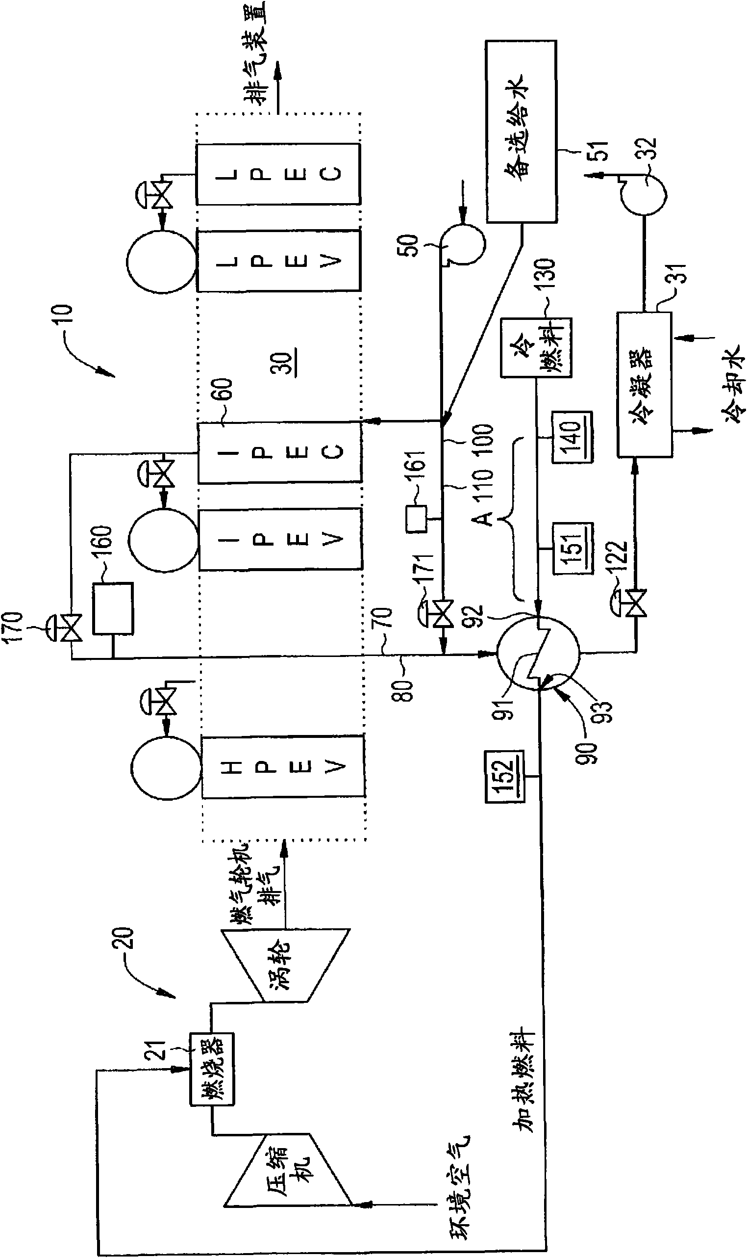
[0051] see Figure 1 to Figure 3 , in a combined cycle power plant (or power plant) 10, fuel and air are combusted in a gas turbine engine 20 to produce mechanical energy, thermal energy, and electricity. A portion of the thermal energy is transferred to a heat recovery steam generator (HRSG) 30 where it is used to generate steam, eg from water condensed in a condenser 31 and pumped by a condensate pump 32 . A portion of the steam is then used to generate additional mechanical energy and / or electricity.

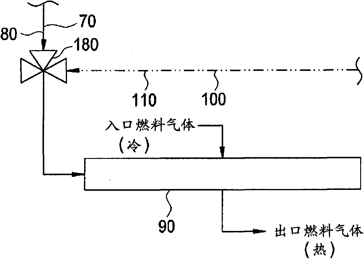
[0052] According to an exemplary embodiment, water recirculated (or regenerated) by HRSG 30 may be directed to feed water pump 50 , which pumps a portion of the recirculated water to, for example, IP economizer 60 of HRSG 30 . This water is heated and output as first feed water 70 at a temperature of approximately 440°F. This first feed water 70 , which is relatively hot, is then fed via a first line 80 towards a heat exchanger 90 where the water can be used to heat the fue...


PUM


Abstract

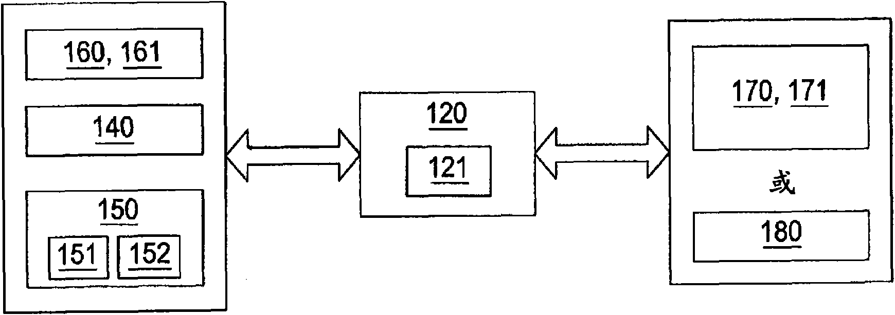
The present invention relates to a fuel heater system including hot and warm water sources. Concretely, a system is provided and includes first and second water supplies (70, 100) at first and second relatively high and low temperatures, respectively; a heat exchanger (90), coupled to the water supplies (70, 100), through which fuel and relative amounts of the water supplies at the first and second temperatures flow for fuel heating; and a controller (120), operably interposed between the water supplies (70, 100) and the heat exchanger (90), to select and / or modulate the relative amounts of the water supplies (70, 100) permitted to flow through the heat exchanger (90) to heat the fuel to a temperature based on a heating requirement to meet a modified wobbe index (MWI) rating.

Description

technical field [0001] The subject matter disclosed herein relates to fuel heating systems using hot and warm water sources. Background technique [0002] Generally, a gas turbine engine includes a compressor, a combustor, and a turbine. Compressors and turbines typically include rows of blades stacked axially in stages. Each stage includes fixed, circumferentially spaced rows of stator blades and a row of rotor blades that rotate about a central axis or axis. In operation, the compressor rotor blades rotate about an axis and act in unison with the stator blades to compress a flow of air. The supplied compressed air is then used in the combustors to combust the supplied fuel. The hot gas flow produced by the combustion expands through the turbine and causes the turbine blades to rotate such that the system as a whole serves to convert the fuel into mechanical energy. [0003] Typically, the feed fuel used in the combustor is preheated to facilitate efficient engine opera...

Claims


Application Information

Patent Timeline
Patent Type & Authority Applications(China)
IPC IPC(8): F02C7/224F02C9/16
CPCY02E20/16F02C9/26F02C7/224F23N2221/10F02C9/40F02C6/18
Inventor T·R·比尔顿D·M·埃里克松R·P·埃卢里帕蒂B·M·加拉赫尔R·西瓦桑卡兰
Owner GENERAL ELECTRIC TECH GMBH
Learn More