

Sewage water source heat exchanger
A technology for heat exchangers and sewage, which can be applied to the types of heat exchangers, indirect heat exchangers, lighting and heating equipment, etc. It can solve the problems of small shell-side flow channels, difficult maintenance, and clogging of debris.
- Summary
- Abstract
- Description
- Claims
- Application Information
AI Technical Summary
Problems solved by technology
Method used
Image

Examples
Embodiment 1
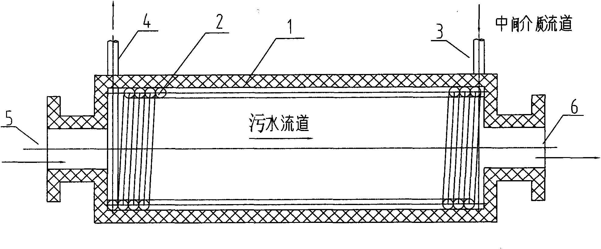
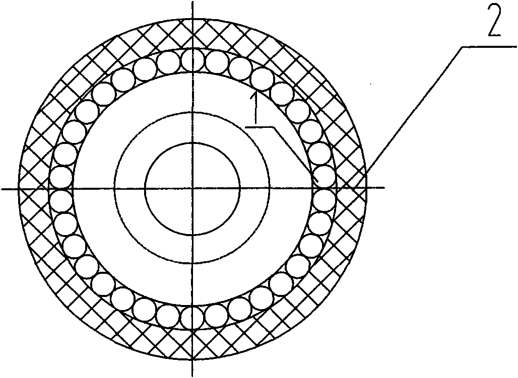
[0020] Such as figure 1 As shown, a sewage water source heat exchanger includes a shell 1 and a heat exchange tube 2. Relative to the central axis of the shell, the heat exchange tube 2 is spirally wound and distributed tightly against the inner wall of the shell 1. One end of the shell 1 is provided with a sewage inlet 5 and an intermediate medium outlet 4, and the other end of the shell 2 is provided with a sewage outlet 6 and an intermediate medium inlet 3. The sewage inlet and outlet pass through the entire shell 1; the heat exchange tube 2 passes through the shell wall with the intermediate medium The inlet and outlet are located at both ends of the shell.
[0021] The shell 1 is one or a group of metal (steel pipe) or non-metal (glass reinforced plastic or other plastics such as PVC, PE and other materials) pipes. The spiral heat exchange tube 2 close to the inner wall of the shell 1 is a group of metal tubes (the material can be copper, copper alloy, stainless steel, etc.)...
Embodiment 2
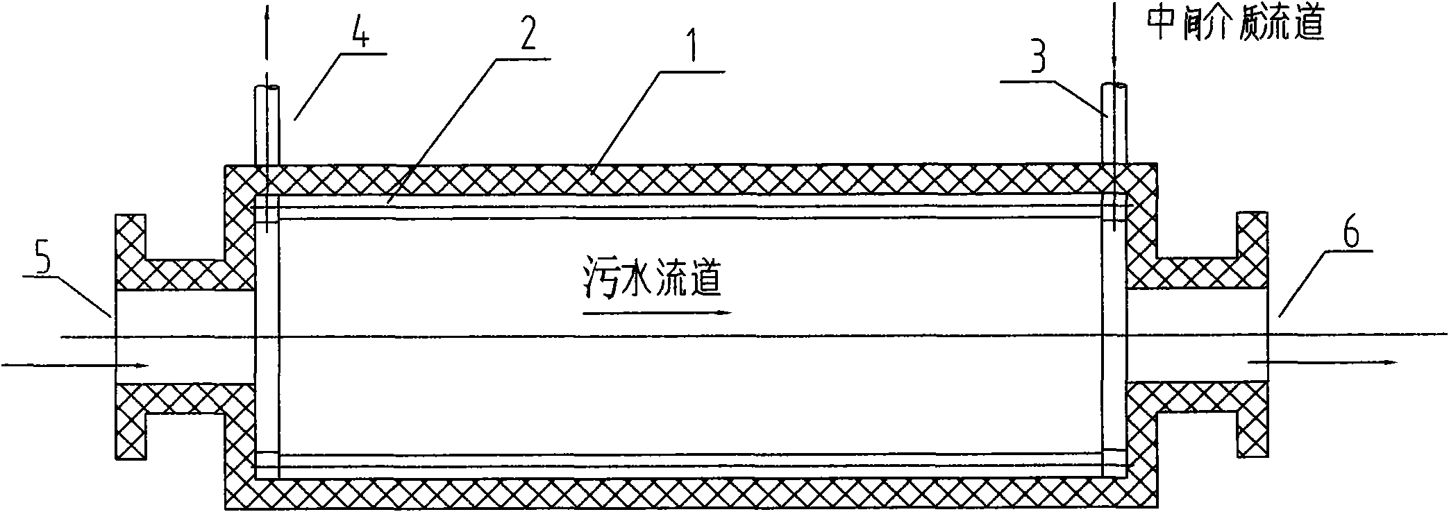
[0024] Such as figure 2 , image 3 As shown, a sewage water source heat exchanger includes a shell 1 and a heat exchange tube 2. Relative to the central axis of the shell, a plurality of heat exchange tubes 2 are distributed in parallel and close to the inner wall of the shell 1, and the two ends of the shell are separately provided One head 7 is connected with each heat exchange tube. One end of the shell 1 is provided with a sewage inlet 5 and an intermediate medium outlet 4 (on one head 7), and the other end of the shell 2 is provided with a sewage outlet 6 and an intermediate medium inlet 3 (on the other head 7). It passes through the entire shell 1; the intermediate medium inlet and outlet of the head 7 are located on the same side of the shell wall and perpendicular to the central axis of the shell 1.
[0025] The shell 1 is one or a group of metal (steel pipe) or non-metal (glass reinforced plastic or other plastics such as PVC, PE and other materials) pipes. The spiral ...
Embodiment 3
[0028] Such as Figure 4 As shown, the heat exchangers of the above embodiments 1 and 2 can be used in the following manner. According to the needs of sewage heat exchange, design the number of heat exchangers and the way of series and parallel connection, Figure 4 It means that 4 heat exchangers are connected in series as a group, in which the sewage channel is connected in series and the intermediate medium (softened water) channel is connected in parallel. Of course, the number of heat exchangers in series is set according to the actual water quality and water treatment capacity, not limited to Figure 4 The combination shown.
[0029] In the operation experiment of a group of small sewage heat pump units in Beijing Gaobeidian Sewage Treatment Plant, 8 figure 1 The heat exchangers shown are connected in series, in which the sewage channels are connected in series and the intermediate medium (softened water) channels are connected in parallel. The designed pumping water flow ra...
PUM
 Abstract
Description
Claims
Application Information