MOS (Metal Oxide Semiconductor) field effect transistor

A field effect transistor, variable technology, applied in semiconductor devices, electrical components, circuits, etc., can solve problems such as cost increase, achieve the effect of good AC characteristics and improve the ability to control short channel effects

Active Publication Date: 2011-08-03
INST OF MICROELECTRONICS CHINESE ACAD OF SCI
View PDF1 Cites 4 Cited by
  • Summary
  • Abstract
  • Description
  • Claims
  • Application Information

AI Technical Summary

Problems solved by technology

Due to the above considerations, many device optimization research and development and patents adopt asymmetric device structure (asymmetric device structure), but asymmetric devices usually require additional lithography masks, which increases the cost, and the process itself is also subject to various constraints. Various constraints (such as the angle of ion implantation, the height and distance of the grid, etc.)

Method used

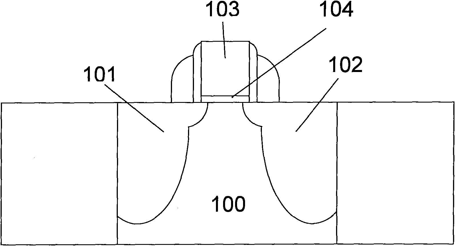
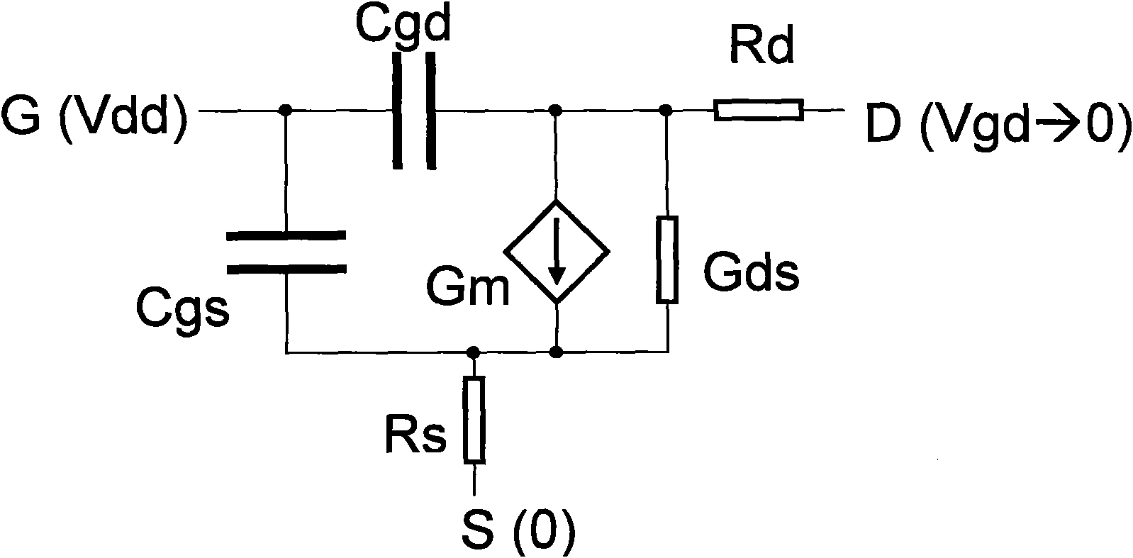
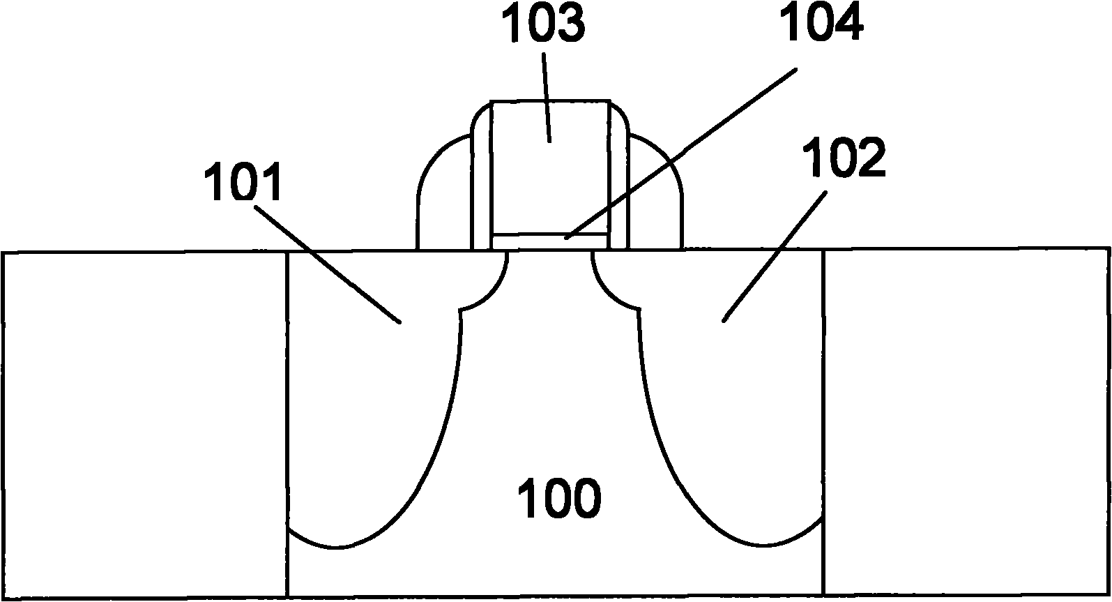

Image

  • MOS (Metal Oxide Semiconductor) field effect transistor
  • MOS (Metal Oxide Semiconductor) field effect transistor
  • MOS (Metal Oxide Semiconductor) field effect transistor

Examples


Embodiment Construction

[0014] Embodiments of the present invention are described in detail below, examples of which are shown in the drawings, wherein the same or similar reference numerals designate the same or similar elements or elements having the same or similar functions throughout. The embodiments described below by referring to the figures are exemplary only for explaining the present invention and should not be construed as limiting the present invention.

[0015] The following disclosure provides many different embodiments or examples for implementing different structures of the present invention. To simplify the disclosure of the present invention, components and arrangements of specific examples are described below. Of course, they are only examples and are not intended to limit the invention. Furthermore, the present invention may repeat reference numerals and / or letters in different instances. This repetition is for the purpose of simplicity and clarity and does not in itself indicat...


PUM


Abstract

The invention provides an MOS (Metal Oxide Semiconductor) field effect transistor comprising a substrate, a source electrode, a drain electrode and a grid stack, wherein the source electrode and the drain electrode are formed in the substrate; the grid stack is formed above the substrate and positioned between the source electrode and the drain electrode; and a grid dielectric layer is made of a dielectric material with an adjustable K value. In the embodiment of the invention, the dielectric material with the adjustable K value is applied to the grid dielectric layer of a CMOS (Complementary Metal-Oxide-Semiconductor Transistor) device; the grid capacitance is increased by dynamically obtaining the high K value; and the capability of the CMOS device on controlling the short channel effect and the switching rate are improved.

Description

technical field [0001] The invention relates to the field of semiconductor design, in particular to the structure of a MOS field effect transistor (MOSFET). Background technique [0002] With the continuous development of semiconductor technology, the feature size of CMOS devices continues to shrink, which causes problems such as short channel effects. Using high dielectric constant (K value) materials (such as HfSiON, HfAlON, etc.) to replace SiO2 to make gate dielectric layers can be used. The current of the device is increased, the driving ability of the device is enhanced, the ability to control the short channel effect is improved, and the further reduction of the device is possible. Existing integrated circuit devices all use dielectric materials with a fixed K value as the gate insulating medium. However, from the perspective of AC performance of the device, not all areas of the gate insulating medium are as high as possible. For example, when a CMOS device is in an ...

Claims


Application Information

Patent Timeline
Patent Type & Authority Applications(China)
IPC IPC(8): H01L29/51H01L29/78
Inventor 陈大鹏梁擎擎
Owner INST OF MICROELECTRONICS CHINESE ACAD OF SCI
Why Eureka
Try Eureka