

Power supply device for electric discharge machine
A technology of electric discharge machine and power supply device, which is used in electric machining equipment, power supply circuit, metal processing equipment, etc., to achieve the effects of high precision machining, stable surface roughness, elimination of unstable motion and internal impedance
- Summary
- Abstract
- Description
- Claims
- Application Information
AI Technical Summary
Problems solved by technology
Method used
Image

Examples
Embodiment approach 1
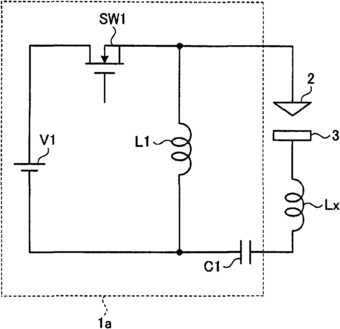
[0035] figure 1 It is a circuit diagram showing the configuration of the power supply device for an electric discharge machine according to the first embodiment of the present invention. in figure 1 Among them, the power supply device 1a for an electric discharge machine is a power supply device in which a machining voltage suitable for finishing conditions is alternately applied to a wire electrode 2 and a workpiece 3 that are arranged facing each other by switching its polarity. Between the electrodes, an arc discharge required for finishing the workpiece 3 is generated between the electrodes.
[0036] The power supply device 1a for an electrical discharge machine and the electrodes are connected by a power cable. There is a lot of parasitic inductance in the vicinity between the electrodes, particularly in the power cable connecting the power supply device 1a for an electrical discharge machine and the electrodes. figure 1 The Lx shown represents the parasitic inductance. in ...
Embodiment approach 2
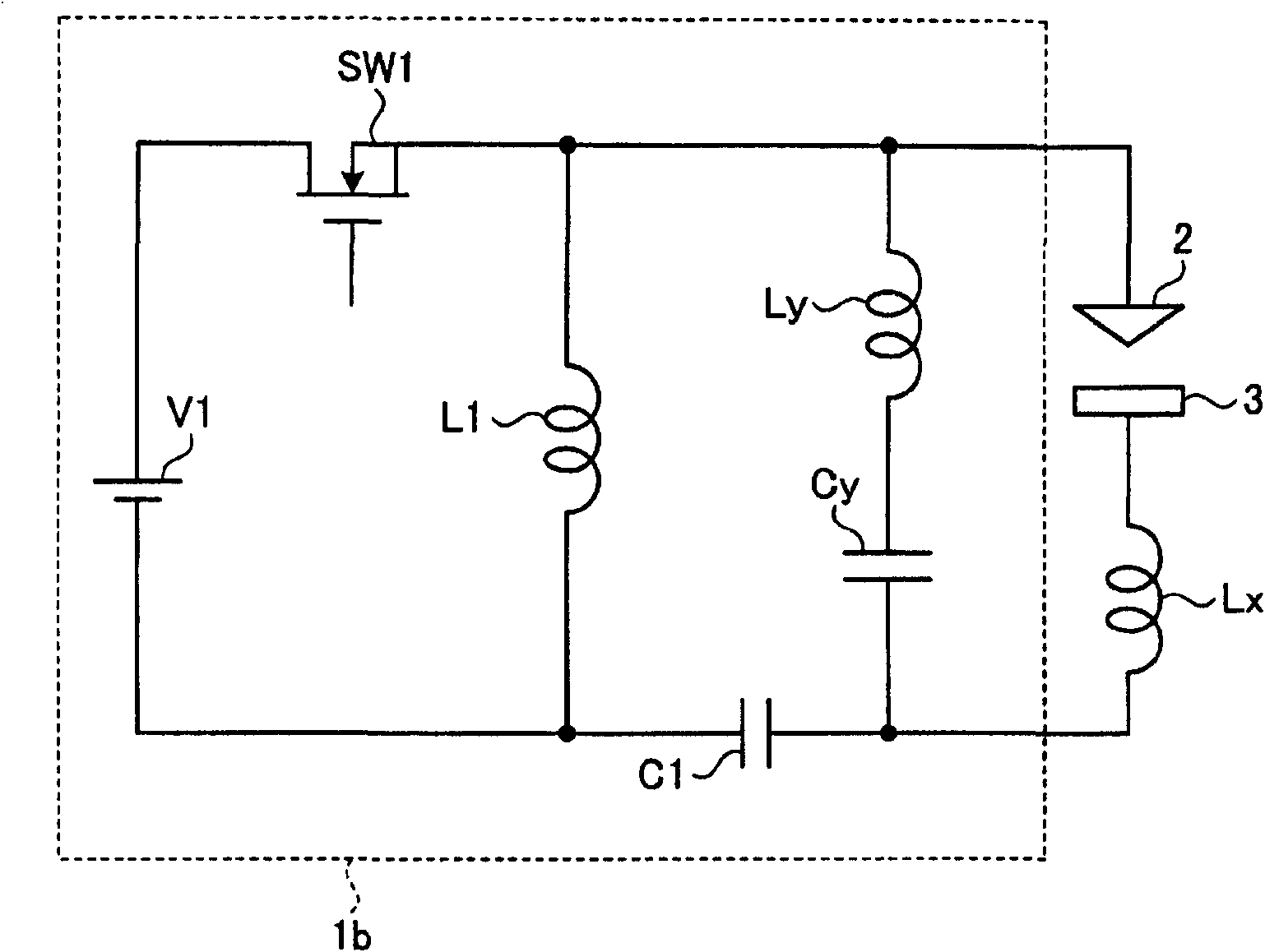
[0056] image 3 It is a circuit diagram showing the structure of a power supply device for an electrical discharge machine according to Embodiment 2 of the present invention. In addition, in image 3 Middle, right and figure 1 The same or equivalent structural elements shown in (Embodiment 1) are given the same reference numerals. Here, the description will focus on the part related to the second embodiment.
[0057] Such as image 3 As shown, the power supply device 1b for an electric discharge machine of the second embodiment is figure 1 In the configuration shown in (Embodiment 1), a series circuit of a capacitor Cy as a capacitive load and a reactor Ly as an inductive load is connected in parallel between the electrodes. The series circuit is a circuit that resonates with the parasitic capacitance between the electrodes.
[0058] In addition, the capacitor Cy is not necessarily in the form of a so-called capacitor, and may be a power supply device other than the power supply d...
Embodiment approach 3
[0065] Figure 5 It is a circuit diagram showing the configuration of a power supply device for an electric discharge machine according to Embodiment 3 of the present invention. In addition, in Figure 5 Middle, right and figure 1 The same or equivalent structural elements shown in (Embodiment 1) are given the same reference numerals. Here, the description will be focused on the parts related to the third embodiment.
[0066] In the first and second embodiments, a case where a high-frequency voltage of the order of MHz is applied between the electrodes is shown using a single switching element. However, it is difficult to increase the frequency of the voltage applied between the electrodes to several MHz to several MHz with one switching element. It is on the order of ten MHz. Therefore, in the third embodiment, a configuration example in which a high-frequency voltage on the order of several MHz to several tens of MHz is applied between electrodes using a plurality of switching ...
PUM
 Abstract
Description
Claims
Application Information