Air film and micro straight channel cooling structure for front edge of hypersonic vehicle

A technology for cooling structures and high-speed aircraft, applied in heat reduction structures, aircraft parts, fuselages, etc., can solve problems such as high surface temperature, inability to meet material strength and service life requirements, and inability to apply, so as to improve heat exchange efficiency Effect

Inactive Publication Date: 2011-08-10
BEIHANG UNIV
View PDF4 Cites 17 Cited by
  • Summary
  • Abstract
  • Description
  • Claims
  • Application Information

AI Technical Summary

Problems solved by technology

Traditional passive cooling, such as radiative cooling, requires a high surface temperature to achieve high radiative heat flux density, so it cannot meet the requirements for material strength and service life. Although the thermal protection structure of the ablation layer can meet the requirements of high heat flux density, However, it cannot be applied to hypersonic vehicles with a flight time of tens of minutes or even hours.

Method used


Image

  • Air film and micro straight channel cooling structure for front edge of hypersonic vehicle
  • Air film and micro straight channel cooling structure for front edge of hypersonic vehicle
  • Air film and micro straight channel cooling structure for front edge of hypersonic vehicle

Examples


Embodiment

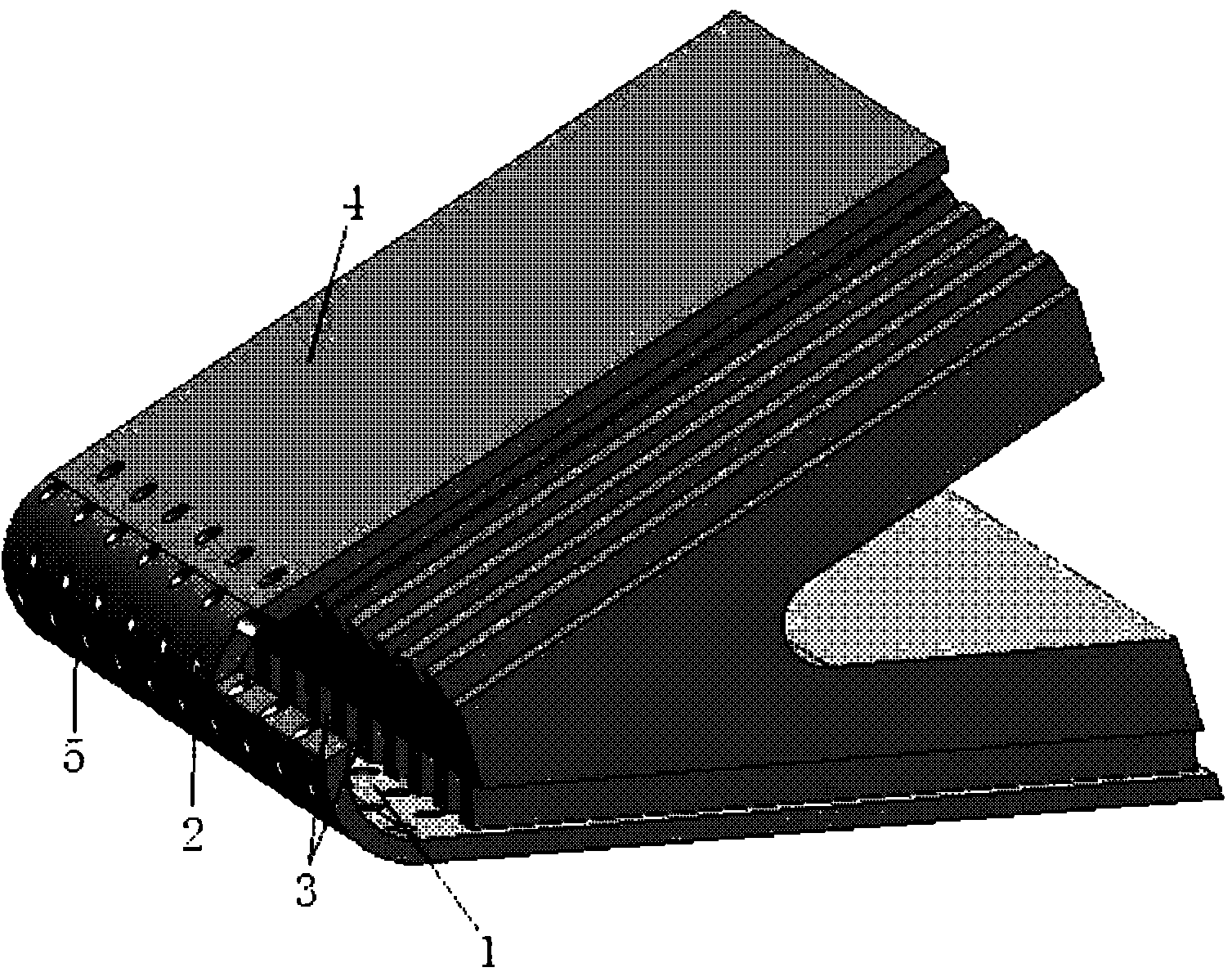
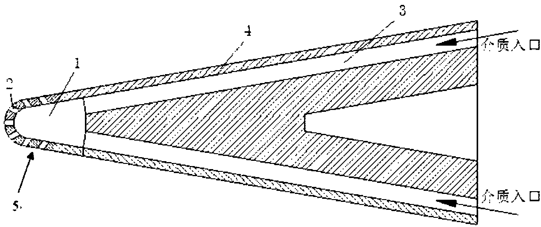
[0019] In the present invention, an air film cavity 1 is opened inside the leading edge of the high-speed aircraft, and an air film hole 2 is opened on the surface near the stagnation point of the leading edge. The diameter of the air film hole 2 is 0.5 mm to 1.0 mm, and the distance between the air film holes 2 is 1.0 mm. mm~2.0mm, open a small straight channel 3 inside the upper and lower surfaces of the wedge-shaped body of the aircraft, and the dimension of the inlet section of the straight channel is (0.5mm~1.0mm)×(0.5mm~1.0mm). The cooling medium water enters from the tiny straight channel at the tail of the aircraft, and flows along the tiny channel towards the front edge. The water is continuously vaporized during the flow process, and a large amount of heat is absorbed from the inner surface of the aircraft during the vaporization process, making the super aircraft wedge-shaped The body surface temperature keeps dropping. When water enters the air film cavity, it is c...


PUM


Abstract

The invention discloses an air film and micro straight channel cooling structure for a front edge of a hypersonic vehicle, which comprises an air film cavity, air film holes and micro straight channels. The air film cavity is positioned inside the front edge of the hypersonic vehicle; the air film holes which are arranged in a stagger mode are formed near stagnation points of the front edge at the periphery of the air film cavity; two rows of micro straight channels are formed next to both upper and lower surfaces of a wedge-shaped body of the hypersonic vehicle; and the micro straight channels are communicated with the air film cavity and a high pressure water tank. On the premise of not changing the pneumatic appearance of the air vehicle, the air film cooling mode is combined with the micro channel cooling mode, so that the heat exchange efficiency is effectively improved.

Description

technical field [0001] The invention relates to a leading edge air film + tiny straight channel cooling structure of a hyper-vehicle, which belongs to the field of local heat exchange with high heat flux density in aviation, aerospace, power machinery and the like. Background technique [0002] The problem of aerodynamic heating is raised because of the need for the research and development of hypersonic vehicles. When the aircraft flies at supersonic or hypersonic speed, the air is subjected to strong compression and severe friction, and most of the kinetic energy is converted into heat energy, causing the temperature of the air around the aircraft to rise sharply. There is a large temperature difference between this high-temperature gas and the surface of the aircraft, and part of the heat energy is quickly transferred to the object surface. This heat transfer method is called aerodynamic heating. The high temperature generated by serious aerodynamic heating will reduce t...

Claims


Application Information

Patent Timeline
Patent Type & Authority Applications(China)
IPC IPC(8): B64C1/38B64C3/36
Inventor 罗翔孙纪宁徐国强张传杰邓宏武
Owner BEIHANG UNIV
Why Eureka
Try Eureka