Pneumatic flotation machine with mechanical stirring

A technology of mechanical stirring and flotation machine, applied in the direction of flotation, solid separation, etc., can solve the problems of low processing capacity, large volume, large consumption of medicine, etc., to achieve enhanced processing capacity, save plant area, and reduce power consumption Effect

Active Publication Date: 2011-08-17
张玮
View PDF9 Cites 6 Cited by
  • Summary
  • Abstract
  • Description
  • Claims
  • Application Information

AI Technical Summary

Problems solved by technology

The disadvantages of the flotation column are: the column is tall, the function of sorting 0.5~0.125mm materials is poor, the processing capacity is poor, and the adaptability is weak
[0008] In summary, the flotation equipment used in China has low processing capacity, weak adaptability, large chemical consumption, bulky size, large workshop space, large power consumption, serious wear, short service life, many auxiliary equipment, and maintenance. Disadvantages of large quantity, high production cost and low degree of automation

Method used


Image

  • Pneumatic flotation machine with mechanical stirring
  • Pneumatic flotation machine with mechanical stirring
  • Pneumatic flotation machine with mechanical stirring

Examples


Embodiment Construction

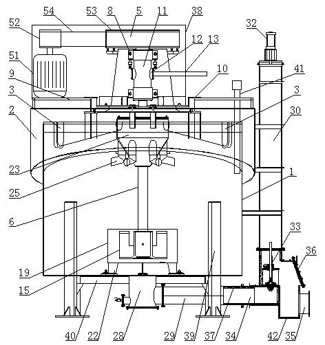
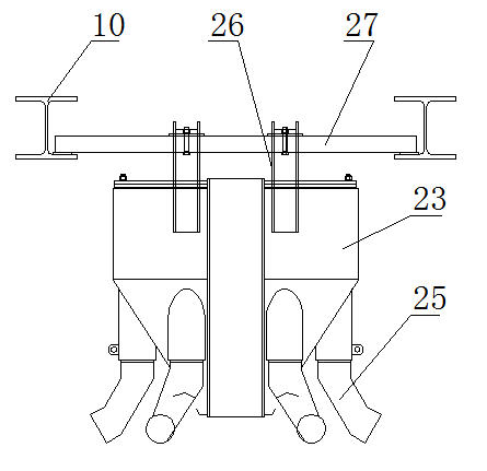
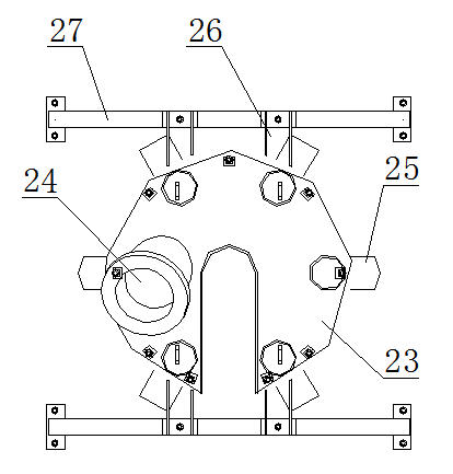
[0039] Such as figure 1 The air-compressed mechanical agitation flotation machine shown includes a cylindrical tank body flotation chamber 1, and a foam product concentration chute 2 is installed on the outer side of the upper end of the flotation chamber 1. The foam product concentration chute 2 has an annular cavity , the upper end of the flotation chamber 1 is provided with a foam product collection chute 3 connected to the cavity of the foam product concentration chute 2; the bottom surface of the foam product concentration chute 2 is an inclined plane, which is convenient for the concentration of the foam product, and the lowest point of the bottom surface is in contact with the clean coal Pipelines (not shown in the figure) are connected and used to transport clean coal outward. In the flotation chamber 1, there is a hollow shaft 6 connected with the driving device 5. The upper part of the hollow shaft 6 is fixed on the support 9 above the foam product concentration chut...


PUM


Abstract

The invention discloses a pneumatic flotation machine with mechanical stirring, which comprises a cylindrical tank body flotation chamber, wherein a foam product collecting chute is closely fastened on the outer side of the upper end of the flotation chamber, and the outer side of the foam product collecting chute is connected with a concentrate pipe; a hollow shaft connected with a driving device is arranged in the flotation chamber, and the hollow shaft is fixed on the support through a bearing and bearing blocks, a bearing housing is arranged between the bearing blocks, an air inlet formedon the bearing housing is connected with an air inlet pipe, and an air inlet is formed on a hollow shaft corresponding to the bearing housing; the lower end of the hollow shaft is connected with a rotor which has an air outlet, and a stator is arranged on the outer side of the rotor; a feed tank is hoisted on the upper part of the flotation chamber, the feed tank is a tank body with an annular cavity, the annular tank body surrounds the outside of the hollow shaft, a feed inlet is formed on the upper part of the feed tank, and discharging nozzles are uniformly arranged on the lower part of the feed tank; and a tailing chamber is formed at the bottom part of the flotation chamber, and the tailing chamber is communicated with a tailing tank through a pipe. The machine is efficient, energy-saving and very adaptable and is long in service life and low in production cost.

Description

technical field [0001] The invention belongs to the technical field of coal preparation equipment, in particular to a compressed air mechanical stirring flotation machine. Background technique [0002] With the change of coal mining method, the proportion of coal slime has increased greatly. In consideration of environmental protection, the country has developed the discharge of coal slime water from the control index discharge to strictly prohibited discharge, forcing the coal preparation plant to match and improve the slime water system and realize the closed circuit of washing water (zero discharge). In order to achieve this goal, the coal preparation plants built in the 1970s and 1980s have been continuously transformed and flotation equipment has been continuously updated. At the same time, my country's coal washing and processing projects are developing rapidly, and the amount of coal washing and washing is increasing continuously. The scale of the plant is gradually ...

Claims


Application Information

Patent Timeline
Patent Type & Authority Applications(China)
IPC IPC(8): B03D1/16
Inventor 万昌梁铁山万建民李伟坡张玮李德仪
Owner 张玮
Why Eureka
Try Eureka