Metallurgical ladle device with vacuum shell

A technology of vacuum shell and package device, applied in metal processing equipment, casting melt container, casting equipment and other directions, can solve the problems of large heat loss of metallurgical package, improve the quality of casting billet, reduce pouring temperature, and shorten blowing time Effect

Active Publication Date: 2013-01-02
武汉市赟巨科技有限公司
View PDF0 Cites 0 Cited by
  • Summary
  • Abstract
  • Description
  • Claims
  • Application Information

AI Technical Summary

Problems solved by technology

[0004] Aiming at the problem of large heat loss in the existing metallurgical ladle, the present invention provides a metallurgical ladle device with a vacuum shell. By setting a vacuum shell on the outer wall of the metallurgical ladle, the heat preservation effect of the metallurgy can be improved, and a reasonable pouring temperature can be ensured. Reduce the temperature drop of molten metal in the pouring process system, and appropriately reduce the discharge temperature of molten metal

Method used


Image

  • Metallurgical ladle device with vacuum shell
  • Metallurgical ladle device with vacuum shell
  • Metallurgical ladle device with vacuum shell

Examples


Embodiment 1

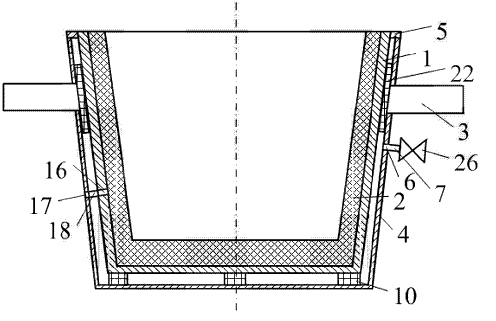
[0027] The structure of metallurgical ladle device with vacuum shell is as follows: figure 1 As shown, including a metallurgical ladle, the metallurgical ladle is mainly composed of a metallurgical cladding 1, a cladding lining 2 and two trunnions 3, each trunnion 3 is fixed on a connecting plate 22, and the connecting plate 22 is fixed on the metallurgical cladding 1 Above, the metallurgical cladding 1 is provided with a plurality of cladding vents 16, and the inner lining 2 is arranged in the metallurgical cladding 1; the outer wall of the metallurgical cladding 1 is provided with a vacuum shell, and the top of the vacuum shell is connected with the metallurgical cladding 1 The top is fixedly connected, and there is a gap between the inner wall of the vacuum shell 1 and the outer wall of the metallurgical cladding to form a vacuum chamber of the shell, and the air pressure in the vacuum chamber is 3Pa; the cladding exhaust hole 16 is connected with one end of the exhaust pipe...

Embodiment 2

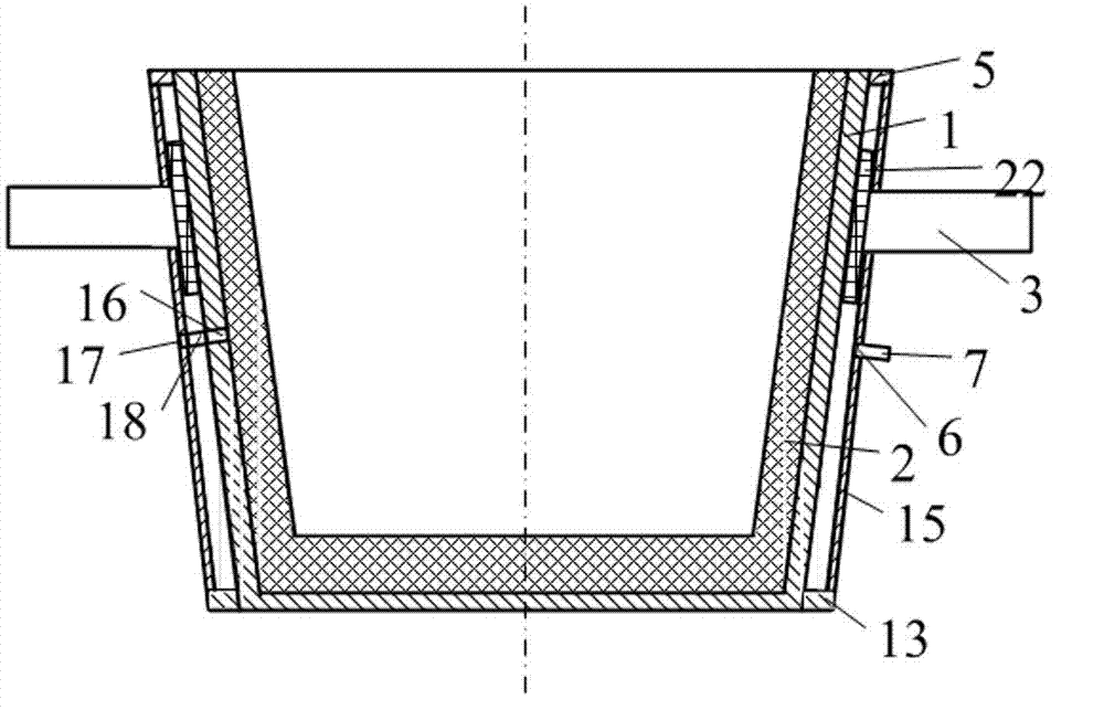
[0037] The structure of metallurgical ladle device with vacuum shell is as follows: figure 2 as shown,

[0038] Including a metallurgical ladle, the metallurgical ladle is mainly composed of a metallurgical cladding 1, a cladding lining 2 and two trunnions 3, each trunnion 3 is fixed on a connecting plate 22, and the connecting plate 22 is fixed on the metallurgical cladding 1, and the metallurgical A plurality of cladding vents 16 are provided on the cladding 1, and the inner lining 2 is arranged in the metallurgical cladding 1; a vacuum shell is provided on the outer wall of the metallurgical cladding 1, and the top of the vacuum shell is fixedly connected to the top of the metallurgical cladding 1 , there is a gap between the inner wall of the vacuum shell 1 and the outer wall of the metallurgical cladding to form a vacuum chamber of the shell, and the air pressure in the vacuum chamber is 4Pa; The vacuum shell exhaust hole 18 on the shell communicates;

[0039] The vacu...

Embodiment 3

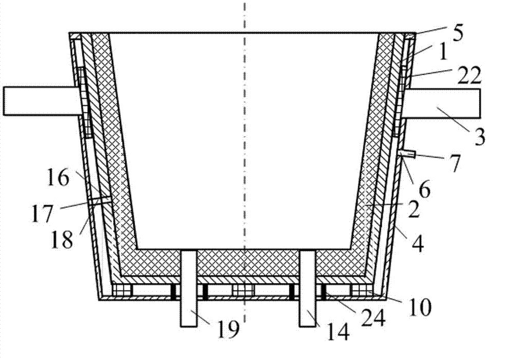
[0047] The structure of metallurgical ladle device with vacuum shell is as follows: image 3 As shown, the structure of the metallurgical ladle is the same as in Embodiment 1, the difference is that: the bottom of the metallurgical ladle is provided with a bottom blowing device hole 14 and a metal liquid flow hole 19, and the structure of the vacuum shell is the same as in Embodiment 1, the difference is that:

[0048] (1) An isolation tube 24 is arranged around the hole 14 of the bottom blowing device and the metal liquid flow hole 16, and two through holes are arranged at the bottom of the barrel wall. The bottom of each isolation tube 24 communicates with a through hole respectively, and the isolation tube 24 The top is connected to the bottom surface of the metallurgical cladding 1, so that the bottom blowing device hole 14 and the metal liquid flow hole 16 are isolated from the vacuum chamber;

[0049] (2) The distance between the inner surface of the cylindrical side wal...


PUM


Abstract

The invention discloses a metallurgical ladle device with a vacuum shell and belongs to the technical field of metallurgical equipment. The vacuum shell is arranged on the outer wall of a metallurgical ladle shell; the top of the vacuum shell is fixedly connected with the top of the metallurgical ladle shell; a gap between the inner wall of the vacuum shell and the outer wall of the metallurgicalladle shell forms a shell vacuum chamber; and the air pressure in the vacuum chamber is 1 to 5Pa. The device has the advantages of low manufacturing cost, long service life, high heat insulation performance, working stability and the like, is suitable for metallurgical ladle, such as foundry ladle, steel ladle or tundish, and can also be suitable for metal liquid ladle or a metal liquid tank in the non-ferrous metallurgical industry.

Description

technical field [0001] The invention belongs to the technical field of metallurgical equipment, in particular to a metallurgical ladle device with a vacuum shell. Background technique [0002] As iron and steel producers pay more attention to the quality and cost of steel production, higher requirements are put forward for metallurgical ladles such as ladles, tundishes, and ladles; The liquid container, especially the secondary refining and continuous casting of the ladle, requires the molten steel to stay longer in the ladle and lower the temperature; in order to meet the strict requirements of the process on materials, it is generally realized by high-end refractory materials, but there is still a temperature drop problems such as large size and high cost. [0003] The ladle is a container for storing molten steel, and it is also an integral part of the refining equipment; molten steel will lose a lot of heat during the transfer and casting process after it is loaded into...

Claims


Application Information

Patent Timeline
Patent Type & Authority Patents(China)
IPC IPC(8): B22D41/00
Inventor 周建安周鹏李旭
Owner 武汉市赟巨科技有限公司
Why Eureka
Try Eureka