Comprehensive dredging machine

A technology of bolter miners and machine heads, which can be applied to cutting machinery, temporary shields, mining equipment, etc. It can solve the problems that accessories are easy to affect production, frequent failures, and low production efficiency, so as to improve time utilization and labor efficiency. Increased productivity, increased safety, and faster cornering effects

Active Publication Date: 2011-08-17
DATONG COAL MINE GRP CO LTD HENGAN EQUIP CO LTD
View PDF5 Cites 37 Cited by
  • Summary
  • Abstract
  • Description
  • Claims
  • Application Information

AI Technical Summary

Problems solved by technology

Drilling and support workers carry the bolter and support materials from the back of the roadheader to the working face to perform work such as bolting, anchoring, manual hanging of metal mesh, and finishing of support. The labor intensity is high, the working hours are long, and the production efficiency is low ( In general, the time for supporting the roof is 2-3 times of the time for cutting coal), and the supporting roof and the tunneling machine for cutting coal cannot realize parallel operation
[0004] 2. Since the support workers work without support (especially when installing anchor plates and laying metal mesh), casualties caused by roof caving and zero-skin collapse occur from time to time
Although individual manufacturers have produced roadheaders with advanced support devices, the problems of low production efficiency, high labor intensity, and insecure safety have not been effectively resolved
[0005] 3. The existing roadheader does not have the function of automatically laying the roof net
[0006] 4. When the existing roadheader, continuous miner, and bolter that trav...

Method used


Image

  • Comprehensive dredging machine
  • Comprehensive dredging machine
  • Comprehensive dredging machine

Examples


Embodiment Construction

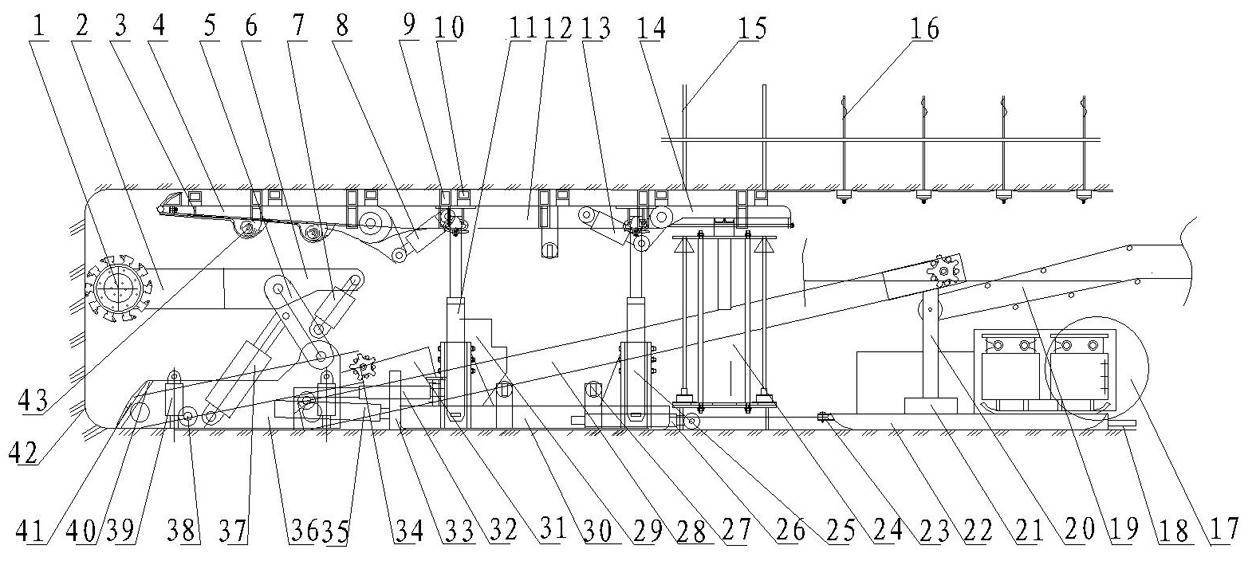
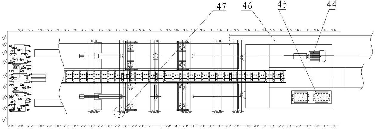
[0034] The comprehensive bolter of the present invention is as figure 1 , figure 2 It consists of a trackless bolter, a hydraulic support, a first scraper conveyor 34, a second scraper conveyor 28, a bridge belt loader 19, a skid 22, a console 29, an electromagnetic starting device 45 and a hydraulic oil pump 44 composed.

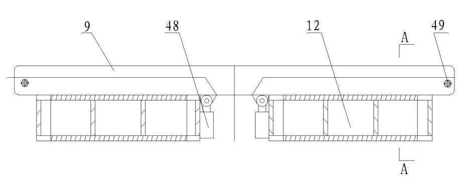
[0035] Among them, the hydraulic support includes a symmetrical left hydraulic support and a right hydraulic support, both of which are composed of a support base box 30, a front and rear bridge 25, a hydraulic column 11, a main top beam 12, a front probe beam 4, a rear probe beam 14 and a crossbeam 9. The hydraulic support belongs to the support type (stack type) hydraulic support. Its main top beam 12 is hinged with the front probe beam 4 and the rear probe beam 14 respectively through the front probe beam jack 8 and the rear probe beam jack 13. The bridge 25 is welded into one body, and the front and rear crossing bridges 25 are both used for connecti...


PUM


Abstract

The invention discloses a comprehensive dredging machine. The comprehensive dredging machine comprises a crawler-free type dredging machine, a hydraulic support, a drilling machine, a scraper conveyor, a runner and the like. The upper end of the hydraulic support is provided with a main top beam, a front canopy, a back canopy and a cross beam; the dredging machine is arranged on a foundation; thefront and rear ends of the foundation are provided with a slope regulation jack respectively; one end of a front pushing and pulling jack is connected with the foundation of the dredging machine, andthe other end of the front pushing and pulling jack is connected with the hydraulic support; the rear of the dredging machine is provided with a self-advancing jack, and two sides of the foundation are provided with a side push cylinder respectively; and the drilling machine is arranged below the main top beam or the back canopy; and the runner is arranged behind the hydraulic support and is connected with a rear push and pull jack arranged on the hydraulic support by an anchor chain and a pulley. The comprehensive dredging machine has the advantages of parallel operation of hole drilling andsupporting, and coal cutting of a development machine, a roadway turns flexibly, the turning radius is small, the turning speed is high, the tunneling speed is high, and the safety is guaranteed.

Description

technical field [0001] The invention relates to a bolter, in particular to a comprehensive bolter with the functions of digging, transporting, supporting, paving and anchoring integrated. Background technique [0002] At present, there are four methods of roadway excavation in the coal industry at home and abroad: one is to adopt the blasting method to excavate; the other is to use the cantilever type roadheader to excavate; Use above-mentioned four kinds of excavation methods and all need coal seam roof to be relatively stable, especially the third, fourth, only can bring into play its peculiar effectiveness under the firm situation of roof. Since the 1980s, my country has successively introduced foreign cantilever roadheaders, continuous miners and a small number of bolter units. However, when using these three types of roadheaders for tunneling, it is necessary to increase the power and increase the deadweight at the same time. Enhance its stability, and the driving effic...

Claims


Application Information

Patent Timeline
IPC IPC(8): E21C25/66E21C25/68E21D23/04E21D19/06E21D9/10E21D9/12
Inventor 吕国安
Owner DATONG COAL MINE GRP CO LTD HENGAN EQUIP CO LTD
Why Eureka
Try Eureka