Power supply circuit for automobile

A technology of power supply circuit and charging circuit, which is applied in the direction of battery circuit devices, electric vehicles, circuit devices, etc., can solve the problems of ignition circuit inoperability, etc., and achieve the effect of starting the engine easily, increasing stability, and prolonging life

Active Publication Date: 2011-08-17
MORNSUN GUANGZHOU SCI & TECH
View PDF8 Cites 26 Cited by
  • Summary
  • Abstract
  • Description
  • Claims
  • Application Information

AI Technical Summary

Problems solved by technology

However, under several amperes of current, the voltage drop is mostly above 0.7V, which makes the voltage obtained by the ignition coil nearly 1V lower than the battery voltage when the switch-type booste

Method used


Image

  • Power supply circuit for automobile
  • Power supply circuit for automobile
  • Power supply circuit for automobile

Examples


Embodiment 1

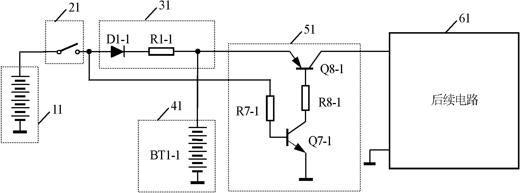
[0058] image 3 The shown embodiment one is a more practical circuit diagram of the present invention, the diode D1-1 and the resistor R1-1 are connected in series to form a charging circuit 31, which is often used in mobile phone chargers; the rechargeable battery BT1-1 forms a battery power supply circuit and The filter circuit 41 is connected to the output end of the charging circuit 31; the resistor R7-1, the NPN transistor Q7-1, the resistor R8-1, and the PNP transistor Q8-1 form a synchronous switch 51, and the emitter of the transistor Q8-1 is connected to the charging circuit 31 The output terminal and the collector are connected to the input terminal of the follow-up circuit 61, the base is connected to the resistor R8-1, the emitter of the triode Q7-1 is grounded, and the collector is connected to the base of the triode Q8-1 through the resistor R8-1. The resistor R7-1 is connected to the input terminal of the charging circuit 31 afterward.

[0059] The working prin...

Embodiment 2

[0068] Figure 4 The second embodiment shown only shows the charging circuit 32, and other functional modules are the same as those of the first embodiment. It is an alternative to the charging circuit in Embodiment 1, such as Figure 4 As shown, the MOS transistor Qt is a P-channel, low-voltage, body-free MOS transistor without a body diode (Body Diode), and its gate is grounded through a resistor Rg, so that its source (S pole) and drain (D pole) are respectively Equivalent replacement for the positive (anode) and negative (cathode) poles of the corresponding diode.

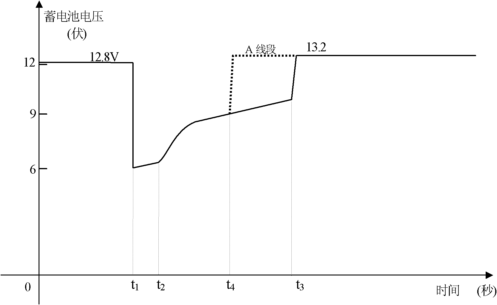
[0069] The working principle of the circuit of this embodiment is: the MOS transistor Qt is a voltage control device, when Figure 4 When connected, the shed of the field effect MOS transistor Qt is grounded through the resistor Rg, and the source voltage is the battery voltage, which is set to 12.8V; at this time, its VGS=-12.8V, which is greater than the turn-on voltage of the MOS transistor, makes the MOS ...

Embodiment 3

[0072] Figure 5 The synchronous switch 53 in the third embodiment shown is a normally open relay RLY, and other functional modules are the same as those in the first embodiment. see Figure 5 After the coil winding of the relay RLY is connected to the original main switch, the other end is grounded; the normally open contact is connected between the rechargeable battery BT1-3 and the follow-up circuit 63 . When the main switch 23 is in the ON state, the relay RLY coil is energized, and the normally open contact becomes closed under the pull-in of the relay, and the voltage of the rechargeable battery BT1-3 is added to the follow-up circuit 63 through the closed contact , the follow-up circuit 63 is energized and works normally.


PUM


Abstract

The invention discloses a power supply circuit for an automobile. The power supply circuit comprises a storage battery (1), a total switch (2) and a following circuit (6), wherein a charging circuit (3), a rechargeable auxiliary power supply circuit (4) and a synchronous switch (5) are connected in series between the total switch (2) and the following circuit (6); the charging circuit (3) is usedfor charging the rechargeable auxiliary power supply circuit (4) by using the storage battery (1); the rechargeable auxiliary power supply circuit (4) is applied to the following circuit (6) by usingthe storage battery (1) when end voltage falls at the starting moment of a starting motor of the automobile so as to ensure normal working voltage of the following circuit (6); the synchronous switch(5) is used for making the rechargeable auxiliary power supply circuit (4) perform power supply and power cutoff synchronously on the following circuit (6) when the total switch (2) is switched on and off. By adopting the power supply circuit, large current is continuously absorbed for the storage battery at the start of an automobile engine, so that an electrical appliance participating in startup is under normal working voltage.

Description

technical field [0001] The invention relates to the field of automobile circuits, in particular to power supply circuits for automobile engine starting, fuel supply and ignition circuits. Background technique [0002] The automobile industry has become one of the pillar industries of the world's major economic countries, and it is now popular in thousands of households. Cars started by humans are now rare and are mostly used for agricultural machinery. All other types of cars have starter motors, which are DC motors. To drive and use a car, the engine must first be started by the starter motor, and the starter motor has an acceleration process from stationary to high-speed rotation until the engine runs normally. During this starting process, the voltage of the battery drops greatly. It is measured that at the moment of starting, that is, the moment the starter motor starts to rotate, the working current is as high as 100 amperes, which makes the instantaneous voltage of t...

Claims


Application Information

Patent Timeline
IPC IPC(8): F02N11/08H02J7/00
Inventor 尹向阳王保均
Owner MORNSUN GUANGZHOU SCI & TECH
Why Eureka
Try Eureka