Heat dissipation method of LED (light-emitting diode) device and device

A technology of LED devices and heat dissipation methods, which is applied in lighting devices, semiconductor devices of light-emitting elements, cooling/heating devices of lighting devices, etc., and can solve problems such as poor heat dissipation effect, high manufacturing cost, and inability to meet the heat dissipation requirements of LED devices. Achieve rapid heat absorption, stable and reliable operation, and low density

Inactive Publication Date: 2011-08-17
SOUTH CHINA UNIV OF TECH
View PDF5 Cites 24 Cited by
  • Summary
  • Abstract
  • Description
  • Claims
  • Application Information

AI Technical Summary

Problems solved by technology

However, the existing technology mainly has shortcomings such as poor heat dissipation effect and high manufacturing cost, which cannot meet the heat dissipation requirements of LED devices.

Method used


Image

  • Heat dissipation method of LED (light-emitting diode) device and device
  • Heat dissipation method of LED (light-emitting diode) device and device
  • Heat dissipation method of LED (light-emitting diode) device and device

Examples


Embodiment 1

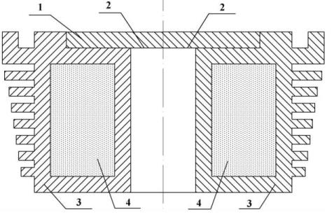
[0028] like figure 2 As shown, this embodiment is suitable for heat dissipation of common LED lighting equipment. The heat dissipation device of the LED device of the present invention comprises a heat dissipation bottom plate 1, a heat conducting sheet 2, and a metal shell 3; the outer surface of the metal shell 3 has annular fins; the annular fins are welded on the metal shell; the heat dissipation bottom plate 1 and the metal shell The body 3 is connected through the heat conducting sheet 2; the metal shell 3 is filled with a composite phase change material 4.

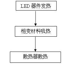
[0029] A composite phase change material of paraffin wax / expanded graphite with a phase change temperature of 52°C is used to fill the metal shell, and the power of the LED lamp is 2W. The heat of the LED lamps is first conducted to the heat dissipation bottom plate, and then the heat dissipation bottom plate transfers the heat to the metal shell. While the outer surface of the metal shell is dissipating heat, the...

Embodiment 2

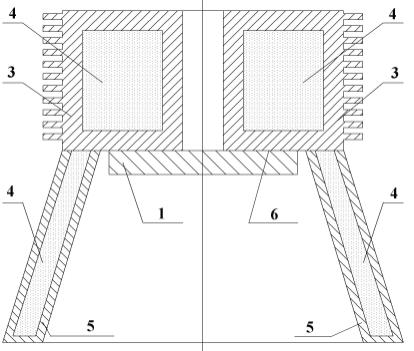
[0031] like image 3 As shown, this embodiment is suitable for heat dissipation of LED lighting equipment with lampshade. The heat dissipation device of the LED device of the present invention comprises a heat dissipation bottom plate 1, a heat conducting sheet 2, a metal shell 3 and a metal cover 5, the outer surface of the metal shell 3 has strip-shaped fins, and the fins and the metal shell are integrally formed at one time; The heat dissipation bottom plate 1 is connected to the metal shell 3 through the heat pipe 6, the condensation end of the heat pipe 6 is connected to the metal shell 3, and the evaporation end of the heat pipe is connected to the heat dissipation bottom plate 1; the metal shell and the metal housing are respectively filled with composite phase change materials 5.

[0032] The metal casing is filled with a paraffin / expanded graphite composite phase change material with a phase transition temperature of 52°C, and the metal housing is filled with a paraff...


PUM

PropertyMeasurementUnit
phase transition temperatureaaaaaaaaaa
phase transition enthalpyaaaaaaaaaa
thermal conductivityaaaaaaaaaa

Abstract

The invention discloses a heat dissipation method of an LED (light-emitting diode) device, which comprises the following steps of: conducting the heat of the LED device into a phase change material which emits heat with the external environment. The invention also discloses a heat sink of the LED device; the heat sink comprises a metal shell, a heat dissipation baseboard and a heat-conducting fin, wherein the metal shell is internally filled with the phase change material, and the heat dissipation baseboard is connected with the metal shell by the heat-conducting fin. The invention also discloses another heat sink of the LED device; the heat sink comprise the metal shell, the heat dissipation baseboard, a heat pipe and a metal outer cover, wherein the metal shell and the metal outer cover are internally filled with the phase change material, and the heat dissipation baseboard is connected with the metal shell by the heat pipe. The phase change materials of the invention is a composite phase change material of an organic matter and an inorganic metal, has faster heat response rate and heat storage capacity, can rapidly absorb the heat generated by the LED device, and controls the junction temperature of the LED device to be within 60 DEG C, thereby avoiding the luminous decay phenomenon caused by the overheating of the LED device and prolonging the service life of the LED device.

Description

technical field [0001] The invention relates to the technical field of heat dissipation of an electric light source, in particular to a heat dissipation method and device for an LED device. Background technique [0002] Countries around the world regard the development and application of LEDs as a key construction project for energy conservation and environmental protection in their own countries, and include them in their national budgets. With the rapid development of LED technology, the calorific value and heat flux density of LED devices have increased significantly. The common application obstacle of LED devices is the high junction temperature of LEDs. At present, the junction temperature of LED devices is still about 70°C, while the optimal junction temperature of LED devices is below 60°C. Excessive junction temperature will lead to a series of problems such as light decay and reduced service life, which makes the application of LED devices restricted. an insurmount...

Claims


Application Information

Patent Timeline
Patent Type & Authority Applications(China)
IPC IPC(8): F21V29/00F21Y101/02F21V29/51F21V29/87F21Y115/10
Inventor 张正国高学农方玉堂徐涛
Owner SOUTH CHINA UNIV OF TECH
Why Eureka
Try Eureka