Burner arrangement for liquid fuels and method for producing burner arrangement

A burner and fuel technology, which is applied in the direction of gas fuel burners, combustion methods, burners, etc., can solve the problems of unsatisfactory satisfaction of the strength criterion, and can not be realized, so as to reduce the limit heat transfer and reduce the metal The effect of thermal bridges

Inactive Publication Date: 2011-08-17
SIEMENS AG
View PDF12 Cites 8 Cited by
  • Summary
  • Abstract
  • Description
  • Claims
  • Application Information

AI Technical Summary

Problems solved by technology

[0011] However, these known proposals, namely to convert a burner to include two combined gas stages and an oil stage, cannot be realized in practice because the strength criteria cannot be satisfied satisfactorily with them

Method used


Image

  • Burner arrangement for liquid fuels and method for producing burner arrangement
  • Burner arrangement for liquid fuels and method for producing burner arrangement
  • Burner arrangement for liquid fuels and method for producing burner arrangement

Examples


Embodiment Construction

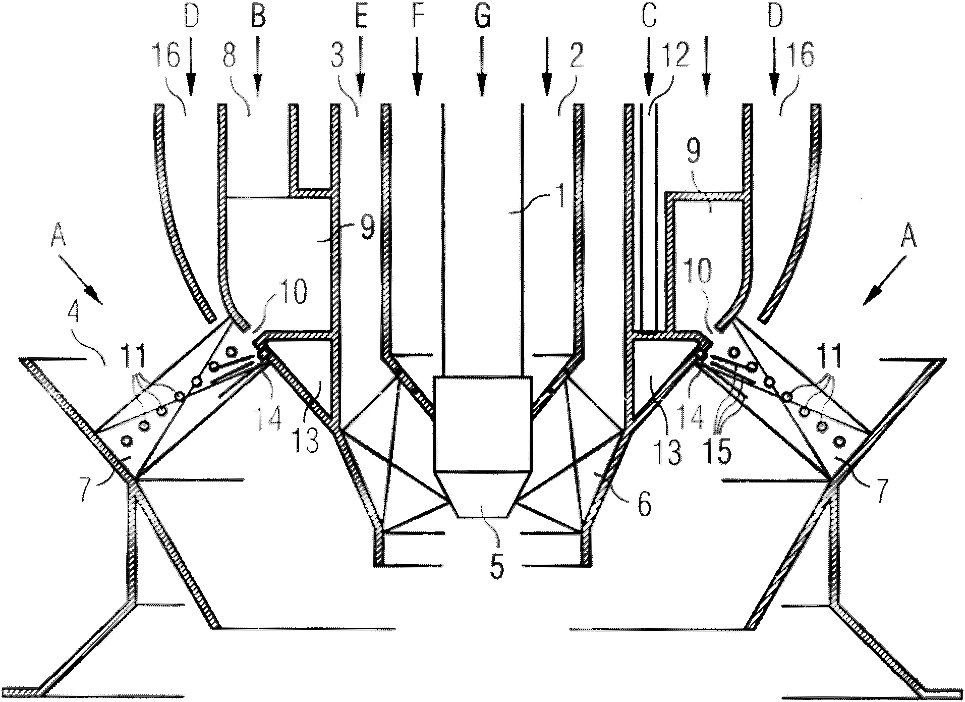
[0036] figure 1 It represents a burner arrangement 20 according to the prior art, which can be installed, for example, in the combustion chamber of a gas turbine arrangement, optionally in connection with a plurality of similar arrangements.

[0037] It consists of an inner section, the control burner system, and an outer section concentric with it and the main burner system. These two systems are suitable for operation with gaseous and / or liquid fuels in any combination. The control burner system consists of a central oil feed 1 (medium G) and an internal gas feed channel 2 (medium F) surrounding it concentrically. The control burner system is in turn surrounded by an inner air inlet channel 3 (medium E) arranged concentrically around the burner axis.

[0038] In or at the channel, a suitable ignition system can be provided, for which many design possibilities are known, so their description is omitted here. The central oil delivery device 1 has an oil injection nozzle 5 a...


PUM


Abstract

The invention relates to a burner arrangement (20) for a firing installation used for firing liquid media, fuels and/or inert materials, in particular heating oil and/or heating gas, wherein at least one medium supply means (1, 2, 8, 9, 12, 13, 16), an air supply means (3, 4) and an air-medium blending means (6, 7), which is designed as a stationary twisted blade (6, 7), are provided for each type of fuel and/or inert material and are arranged in the walls of a contiguous metallic burner housing. At least one medium supply means (9, 13, 16) is separated from the adjoining regions of the burner housing along the respective separating wall by at least one recessed, particularly adiabatic interspace (33, 43) so that the heat exchange between adjoining regions of the burner housing, in particular between the adjacent medium supply means (9, 13, 16), is reduced in the regions of the recessed adiabatic interspaces (33, 43). Furthermore, at least two medium supply means (9, 13, 16) are designed as individual modular units (30, 40, 50).

Description

technical field [0001] The invention relates to a burner arrangement of a combustion plant for burning a fluid medium and to a method of producing a burner arrangement having the features stated in the preambles of the respective independent claims. Background technique [0002] In view of the worldwide efforts to reduce the emissions of harmful substances from combustion plants, especially from gas turbines, burners have been developed in recent years which have particularly low emissions of nitrogen oxides (NOx). It is of great concern in this respect that the burners can be operated not only with one fuel, but as far as possible with different fuels, such as oil, natural gas and / or gas, by choice or in combination, in order to increase the security of supply and to work flexibly sex. Such a burner is described, for example, in EP0276696B1. [0003] One of the difficulties in designing a burner for all possible different usage conditions and motive fuels is that the spec...

Claims


Application Information

Patent Timeline
Patent Type & Authority Applications(China)
IPC IPC(8): F23R3/28F23R3/36F23L7/00F23D14/78
CPCF23L7/00F23D14/78F23R3/36F23R2900/00002F23R2900/00017F23D2900/00017F23R3/283Y02E20/30
Inventor 安德烈亚斯·贝彻马里亚诺·卡诺沃尔夫安德烈·克卢格托拜厄斯·克里格萨沙·斯塔林乌尔里克·沃尔兹
Owner SIEMENS AG
Why Eureka
Try Eureka