Supercharge Your Innovation With Domain-Expert AI Agents!

Control method for power control circuit, power supply unit, power supply system, and power controller control method

A power supply control circuit and circuit technology, which is applied in control/regulation systems, emergency protection circuit devices, power supply testing, etc., can solve problems such as heat loss, non-generation, and device stop, and achieve accurate short-circuit faults and accurate detection.

Inactive Publication Date: 2011-08-17
FUJITSU LTD
View PDF6 Cites 23 Cited by
  • Summary
  • Abstract
  • Description
  • Claims
  • Application Information

AI Technical Summary

Problems solved by technology

That is, the entire device may stop due to a short-circuit fault
[0011] Moreover, in the existing protection circuit, when an impedance fault occurs, the voltage effect of the current sensing resistor Rsense1 (or current sensing resistor Rsense2) is very small or does not occur, so the impedance fault cannot be detected
As a result, there is a problem of causing heat loss

Method used


Image

  • Control method for power control circuit, power supply unit, power supply system, and power controller control method
  • Control method for power control circuit, power supply unit, power supply system, and power controller control method
  • Control method for power control circuit, power supply unit, power supply system, and power controller control method

Examples


Embodiment 1

[0047] [Outline of power supply control circuit]

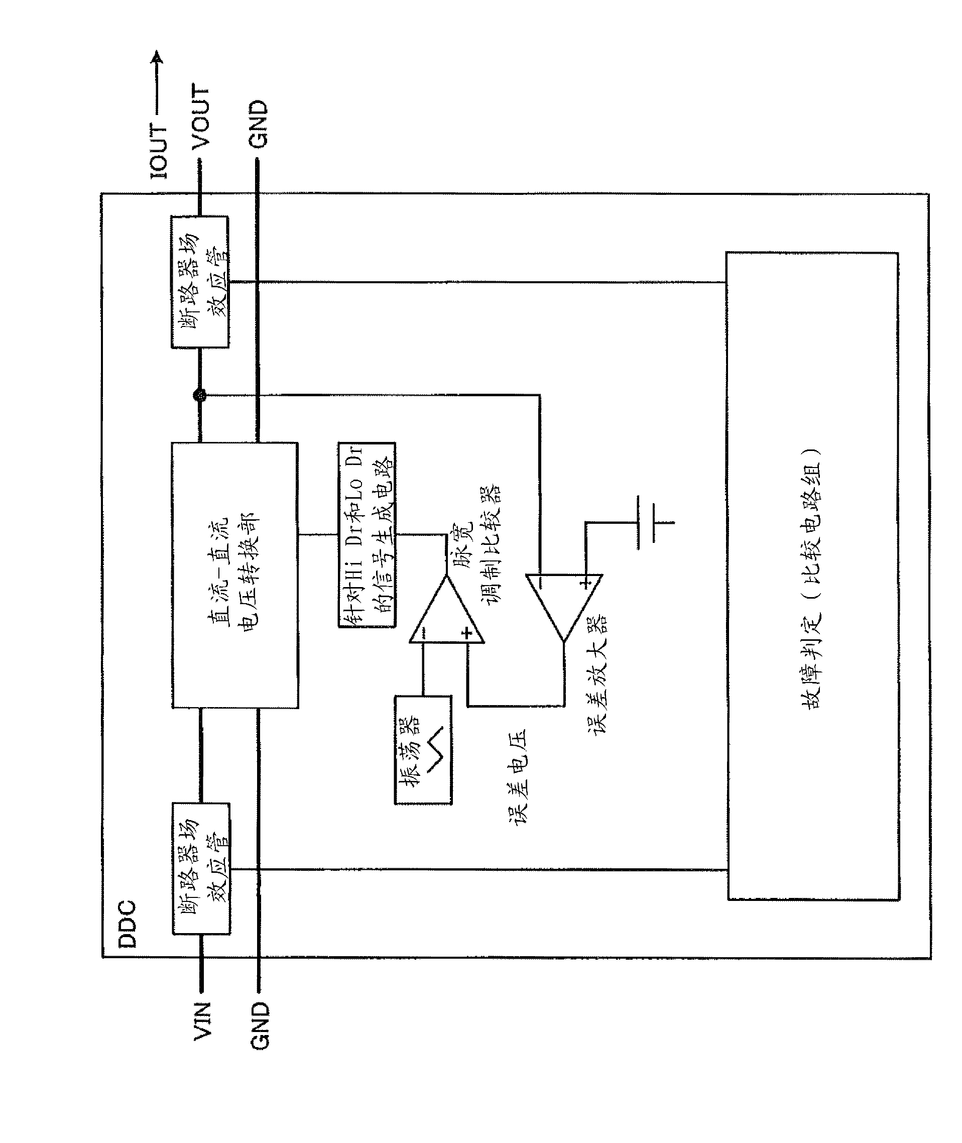
[0048] First, use figure 1 The outline of the power supply control circuit of the first embodiment will be described. figure 1 is a diagram showing a DDC converter including the power supply control circuit of the first embodiment.

[0049] Such as figure 1 As shown, the DDC converter is a device that converts the input voltage VIN to VOUT (load current IOUT) through the DC-DC voltage conversion unit and outputs it, and is the following DC-DC converter (DC / DC Converter: DC-DC conversion devices) (such as switching DC-DC converters, etc.): With the progress of miniaturization, mobile devices such as information processing devices using low-voltage LSIs, and high-functioning mobile phones and electronic devices have been realized. power saving and light weight.

[0050] In addition, the error amplifier "Error AMP" and "PWM COMPARATOR" are connected to the DC-DC voltage conversion part. The "Error AMP" always compares the ...

Embodiment 2

[0149] Embodiment 1 has been described above, but this embodiment can be implemented in various forms other than the above-described embodiments. Therefore, as shown below, different embodiments will be described by distinguishing (1) parallel configuration, (2) circuit configuration, and the like.

[0150] (1) Parallel structure

[0151] For example, in Embodiment 1, a DDC to which the power supply control circuit disclosed in the present application is applied is used as an example for description, however, as Figure 25 As shown, n+1 DDCs (DDC0 to DDCn) to which the power supply control circuit disclosed in the present application is applied can also be connected in parallel. Usually, when general power supply control circuits are connected in parallel, if one of them fails, the input voltage and output voltage are introduced to the failed DDC and lowered, thereby stopping the power supply or load of the entire device. Therefore, in a structure in which n+1 units (DDC0 to...


PUM


Abstract

The present invention provides a control method for power control, power supply unit, power supply system, and power controller. A power control circuit, in a short-circuit fault of ''Lo Side FET'', detects a reference voltage (VD) which is the intermediate voltage between ''Hi Side FET'' and ''Lo Side FET'' and compares a threshold ''VIN-VrefH'' and the VD by use of a comparator (COMP)with each other. When the reference voltage (VD) is smaller than the threshold ''VIN-VrefH'' and a switching control signal (Hi Dr) is ON, the power control circuit judges that the short-circuit fault occurs. Similarly, the power control circuit, in a short-circuit fault of ''Hi Side FET'', detects the reference voltage (VD) between ''Hi Side FET'' and ''Lo Side FET'' and compares a threshold ''VrefL'' and the VD by use of a comparator (COMP)with each other. When the reference voltage (VD) is larger than the threshold ''VrefL'' and a switching control signal (Lo Dr) is ON, the power control circuit judges that the short-circuit fault occurs.

Description

technical field [0001] The invention relates to a power supply control circuit, a power supply device, a power supply system and a control method of the power supply control device. Background technique [0002] Conventionally, rectifying FETs (Field Effect Transistors: Field Effect Transistors) such as "Hi Side FETs" or "Lo Side FETs" have been used as power sources used in various electronic devices including information processing devices. [0003] For specific examples, such as Figure 27 As shown, a non-isolated DC-DC converter step-down circuit (switching control method) with input power supply, input capacitor, smoothing inductor, smoothing capacitor, load, Hi Side FET, Lo Side FET, inverter, etc. is used. This non-isolated DC-DC converter step-down circuit conducts on / off the input current by switching control signals (Hi Dr or Lo Dr) output from the Hi driver or Lo driver, and through smoothing inductors, smoothing capacitors, loads, The voltage / current is averaged...

Claims


Application Information

Patent Timeline
IPC IPC(8): H02M3/155
CPCY02B70/1466G01R31/40H03K17/18H02H7/1213H02M1/32H02M3/1588Y02B70/10G05F1/10H02M3/155
Inventor 板仓和彦
Owner FUJITSU LTD
Features
  • R&D
  • Intellectual Property
  • Life Sciences
  • Materials
  • Tech Scout
  • Unparalleled Data Quality
  • Higher Quality Content
  • 60% Fewer Hallucinations
Learn More