Vena cava filter

A vena cava and filter technology, applied in the direction of the filter in the blood vessel, can solve problems such as thrombus blockage

Inactive Publication Date: 2011-08-24
BEIHANG UNIV
View PDF7 Cites 0 Cited by
  • Summary
  • Abstract
  • Description
  • Claims
  • Application Information

AI Technical Summary

Problems solved by technology

[0003] The purpose of the present invention is to design a new type of filter whose placement direction is opposite to that of the traditional filter, aiming at the current problem that the vena cava filter is blocked by thrombus after being inserted.

Method used


Image

  • Vena cava filter
  • Vena cava filter
  • Vena cava filter

Examples


Embodiment Construction

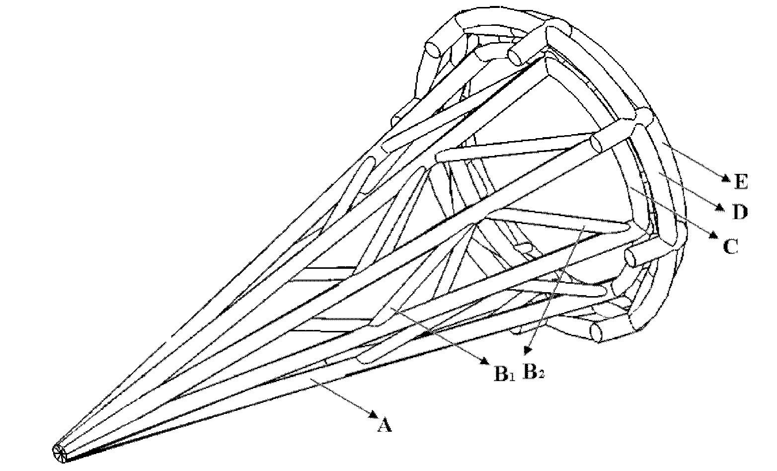
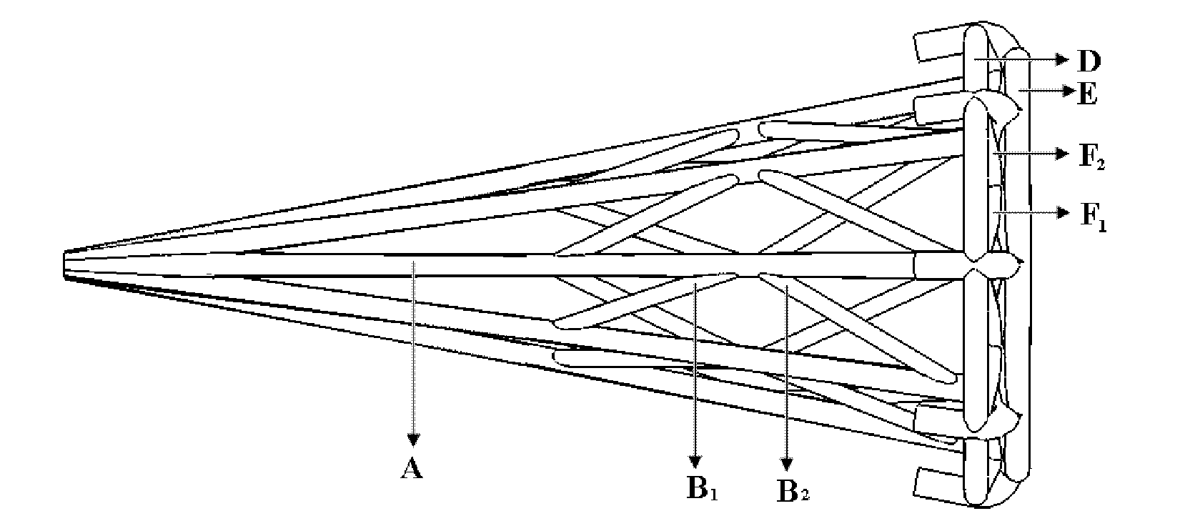
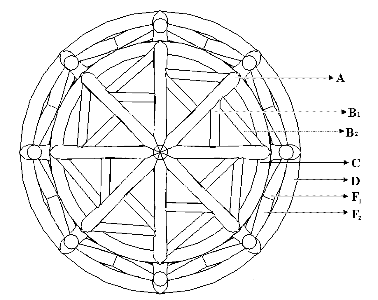
[0018] Below in conjunction with accompanying drawing and specific embodiment the present invention is described in further detail:

[0019] Such as figure 1 , figure 2 , image 3 , Figure 4 Shown: the present invention mainly is by A, B 1 B 2 , C, D, E, F 1 f 2 , G A total of seven parts similar to the "umbrella" or conical vena cava filter. The specific composition and structure of each part has been described in detail in the accompanying drawings. In clinical application, the placement direction of the vena cava filter is opposite to that of the traditional vena cava filter, and the position of collecting thrombus is different from that of the traditional vena cava filter. , but collect the thrombus in a circular position close to the wall of the vena cava (such as figure 1 , figure 2 , image 3 , Figure 4 The area between the circular underhook area on the bottom of each foot in part A and the area between the rings of C, D, E, plus F 1 f 2 , the area ...


PUM


Abstract

The invention provides a vena cava filter which is characterized in that the arrangement direction of the vena cava filter is opposite to the arrangement direction of a traditional vena cava filter; and the position for collecting thrombi by using the vena cava filter provided by the invention is different from the position for collecting thrombi by using the traditional vena cava filter, wherein the thrombi are collected in a low-shear-force pointed region near the central axis of the vena cava vessel by using the traditional vena cava filter, and the thrombi are collected in a high-shear-force annular region close to the wall surface of the vena cava vessel by using the vena cava filter provided by the invention. As shown in the specification, the filter comprises seven parts including A, B1B2, C, D, E, F1F2 and G, the filter is similar to an umbrella shape or a cone shape, and all parts are composed of filaments the diameters of which are 0.5-1mm. By adopting the filter and scheme provided by the invention, the shear force acting on the thrombi captured by the vena cava filter can be improved, and the dissolution rate of the captured thrombi can be increased, thereby effectively lowering the probability of occurrence of a clogging event of the vena cava filter, and prolonging the service time of the vena cava filter. Thus, the vena cava filter provided by the invention has an important clinical application value.

Description

technical field [0001] The invention relates to a cardiovascular interventional device, more specifically, a new type of vena cava filter whose placement direction is opposite to that of a traditional vena cava filter (such as the attached Figure 6 shown). Background technique [0002] The vena cava filter is an interventional device used to prevent the thrombus formed in the deep vein of the patient's body from flowing into the heart and lungs, and it can effectively prevent pulmonary embolism. However, after the vena cava filter is inserted, as more and more blood clots are captured, the filter will often be blocked, resulting in blockage of the entire vena cava, and venous blood cannot flow back into the heart. Therefore, surgery must be performed to remove the filter and replace it again. Insert a new filter. Although the vena cava filter has been developed to the second generation, it is possible to send the filter into the vena cava through a guide wire in a minimall...

Claims


Application Information

Patent Timeline
Patent Type & Authority Applications(China)
IPC IPC(8): A61F2/01
Inventor 陈增胜邓小燕樊瑜波
Owner BEIHANG UNIV
Why Eureka
Try Eureka