Design method for reconstructing diversion tunnel into flood discharge tunnel in 'tail-raising' mode

A design method and technology of diversion tunnels, applied in the field of flood discharge tunnels, can solve problems such as high construction technology requirements, high cost, and complex stress, and achieve the effect of easy construction technology, construction technology operation, and simple structure in the tunnel

Active Publication Date: 2011-08-24
POWERCHINA XIBEI ENG
View PDF3 Cites 15 Cited by
  • Summary
  • Abstract
  • Description
  • Claims
  • Application Information

AI Technical Summary

Problems solved by technology

[0004] Regardless of the traditional dragon head type, or the horizontal swirl and vertical shaft swirl types that have appeared in recent years, this kind of plan for transformation and utilization at the entrance is adopted. The water flow in the cave is generally an open flow, with high velocity a

Method used


Image

  • Design method for reconstructing diversion tunnel into flood discharge tunnel in 'tail-raising' mode
  • Design method for reconstructing diversion tunnel into flood discharge tunnel in 'tail-raising' mode
  • Design method for reconstructing diversion tunnel into flood discharge tunnel in 'tail-raising' mode

Examples


Embodiment 1

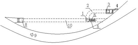
[0023] A flood discharge tunnel converted from a diversion tunnel using the "dragon tail" type, including: a water inlet tower 8, a diversion tunnel 10, a shaft section 1, a horizontal turning section 2, a sluice section 3 and a downstream energy dissipation section 4 The water inlet tower 8 communicates with the front end of the diversion tunnel 10, the diversion tunnel 10 is connected to the vertical shaft section 1 at the end of the joint section, the upper end of the vertical shaft section is connected to the front end of the horizontal turning section 2, and the lower end of the vertical shaft section 1 is connected to the hole of the diversion tunnel 10 The body is connected, and the end of the horizontal turning section 2 is provided with a sluice chamber section 3 and a downstream energy dissipation section 4 .

Embodiment 2

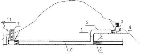
[0025] A flood discharge tunnel converted from a diversion tunnel using the "dragon tail" type, including: a water inlet tower 8, a diversion tunnel 10, a shaft section 1, a horizontal turning section 2, a sluice section 3 and a downstream energy dissipation section 4 The water inlet tower 8 communicates with the front end of the diversion tunnel 10, the diversion tunnel 10 is connected to the vertical shaft section 1 at the end of the joint section, the upper end of the vertical shaft section is connected to the front end of the horizontal turning section 2, and the lower end of the vertical shaft section 1 is connected to the hole of the diversion tunnel 10 The end of the horizontal turning section 2 is provided with a sluice chamber section 3 and a downstream energy dissipation section 4; the end of the diversion tunnel 10 is provided with a blocking section 5; or the water inlet tower 8 is provided with The water inlet 7 in the later stage; or the conical valve 6 is arrange...

Embodiment 3

[0027] Such as figure 1 and figure 2 As shown, a flood discharge tunnel converted from a diversion tunnel using the "dragon tail" type, including: water inlet tower 8, diversion tunnel 10, shaft section 1, horizontal turning section 2, sluice chamber section 3 and downstream extinguishing tunnel The energy section 4, the horizontal turning section 2 and the diversion tunnel 10 are respectively parallel to the horizontal plane. The tail of the diversion tunnel 10 is connected to the shaft section 1, and the lower end of the shaft section 1 communicates with the body of the diversion tunnel 10 to reduce the upstream water level 11 and The water head at the downstream outlet is poor, and the front end of the diversion tunnel 10 is connected with a water inlet tower 8, and the water inlet tower 8 is provided with a later stage water inlet 7, and the later stage water inlet 7 and the water inlet tower 8 are arranged on the upstream of the river 9; The upper end of the shaft secti...


PUM


Abstract

The invention relates to a design method for reconstructing a diversion tunnel into a flood discharge tunnel in a 'tail-raising' mode. The design method is used for reconstructing the diversion tunnel into the flood discharge tunnel in the 'tail-raising' mode, wherein, a vertical shaft section and a horizontal turning section are additionally arranged at the tail of the diversion tunnel so that the horizontal height of the horizontal turning section is higher than that of the diversion tunnel. The design method has the advantages that the flood discharge tunnel reconstructed by the design method has a simple structure, and the construction process is easy to operate; stress state of an operating gate can be improved; and the problem of downstream energy dissipation is easily solved, and the manufacturing cost is lowered.

Description

technical field [0001] The invention relates to a flood discharge tunnel, in particular to a design method for a flood discharge tunnel reconstructed from a diversion tunnel using a "dragon tail" pattern. Background technique [0002] In water conservancy and hydropower projects, the cost of a diversion tunnel is as high as tens of millions or even hundreds of millions of yuan. After the construction diversion is completed, it is often transformed into a flood discharge tunnel, sand discharge tunnel, diversion tunnel, etc., and transformed into a flood discharge tunnel. It is the most used in my country's hydropower projects. In the past, the dragon head type was often used. In recent years, new types such as horizontal swirl and vertical shaft swirl have appeared. [0003] The idea of ​​transforming the above-mentioned diversion tunnel into a flood discharge tunnel, considering the safety of the tunnel itself and reducing the force on the gate, is to control the water flow a...

Claims


Application Information

Patent Timeline
IPC IPC(8): E02B8/06
Inventor 任苇
Owner POWERCHINA XIBEI ENG
Why Eureka
Try Eureka