LED lamp manufacturing method

A technology of LED lamps and manufacturing methods, which is applied to the cooling/heating devices of lighting devices, lighting and heating equipment, electrical components, etc., and can solve the problems of poor heat dissipation effect of LED light source parts, low production efficiency, and many heat-conducting layers of lamps. To facilitate the operation of automated equipment, reduce the use of materials, and solve the effect of light decay

Inactive Publication Date: 2011-08-24
惠州志能达光电科技有限公司
View PDF4 Cites 10 Cited by
  • Summary
  • Abstract
  • Description
  • Claims
  • Application Information

AI Technical Summary

Problems solved by technology

This type of lamp must use silver glue to solidify the crystal between the LED chip and the heat dissipation part when the LED chip is packaged, forming a layer of thermal resistance. At the same time, an insulating material is used between the LED chip and the aluminum substrate, thus forming a second layer. Thermal resistance, and there is also a heat dissipation paste between the LED chip and the heat dissipation component, thus forming a third layer of thermal resistance. Therefore, the lamp with this structure has many heat conduction layers, high thermal resistance, and the heat dissipation effect of the LED light source part is poor. , LED chips are prone to light decay
At the same time, it can be seen that the lamps with this structure have many manufacturing processes and materials, and it is not easy to carry out automatic production, and the production efficiency is low and the production cost is high.

Method used


Image

  • LED lamp manufacturing method
  • LED lamp manufacturing method
  • LED lamp manufacturing method

Examples


Embodiment Construction

[0020] In order to facilitate the understanding of those skilled in the art, the structural principle of the present invention will be further described in detail below in conjunction with specific embodiments and accompanying drawings:

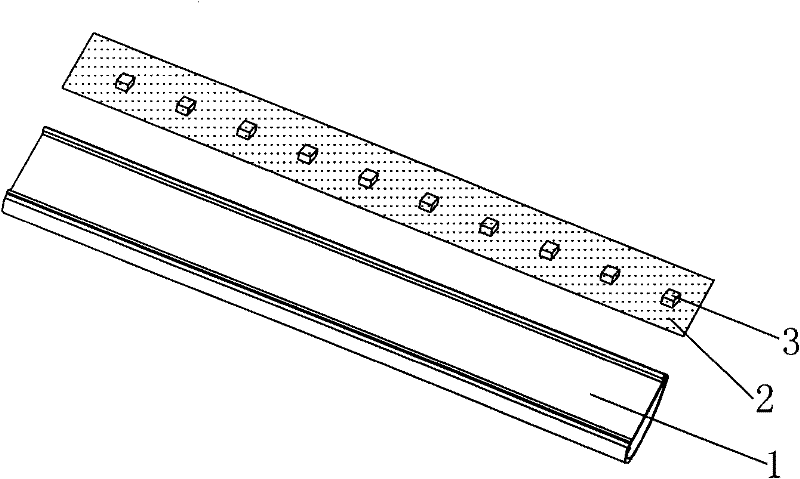
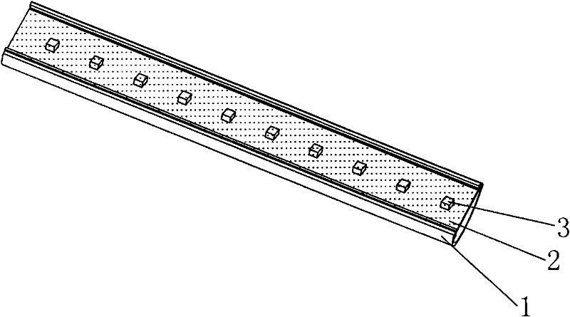
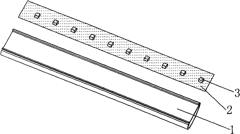
[0021] as attached figure 1 As shown, the LED lamp in this embodiment is mainly composed of a heat dissipation housing 1 , an LED chip 2 and a flexible circuit board 3 . Wherein, the heat dissipation casing 1 can be a copper casing, an aluminum casing, a magnesium-aluminum casing, a ceramic casing, or a magnesium-copper casing, and wires electrically connected to external circuits are arranged on the flexible circuit board 3 .

[0022] In this embodiment, in order to realize that the lamp has the advantages of small thermal resistance, high production efficiency, and low cost, the lamp is produced by the following method:

[0023] a. Pre-attach a layer of heat-conducting medium to the position where the LED chip needs to be installed on the ...


PUM


Abstract

The invention relates to an LED lamp manufacturing method. An LED lamp includes a heat radiation housing, an LED chip and a pliable circuit board provided with a lead. The manufacturing method includes the steps of pasting a layer of heat-conducting medium on a position of the heat radiation housing in advance, while the position is assigned to install the LED chip; pasting the pliable circuit board on the heat-conducting medium; fixing the LED chip on the pliable circuit board in a die-attaching manner; welding the LED chip and the lead of the pliable circuit board so as to realize the electricity conduction; and sealing the LED chip and the pliable circuit board by silica gel and phosphor powder. Compared with the prior art, the LED lamp manufacturing method to manufacture high quality products solves the problem of light decay caused by poor heat radiation of the LED lamp, and has the advantages of simplified working process, high production efficiency, and low material consumption and cost. The LED lamp manufacturing method can adopt the automatic equipments to operate, thus further improving the production efficiency.

Description

technical field [0001] The invention belongs to the technical field of lamps, and specifically refers to a method for manufacturing an LED lamp. Background technique [0002] In the manufacture of existing LED lighting fixtures, the LED light source part and the heat dissipation part are two independent parts, and they must be combined with connecting materials to make a complete LED lamp. This type of lamp must use silver glue to solidify the crystal between the LED chip and the heat dissipation part when the LED chip is packaged, forming a layer of thermal resistance. At the same time, an insulating material is used between the LED chip and the aluminum substrate, thus forming a second layer. Thermal resistance, and there is also a heat dissipation paste between the LED chip and the heat dissipation component, thus forming a third layer of thermal resistance. Therefore, the lamp with this structure has many heat conduction layers, high thermal resistance, and the heat diss...

Claims


Application Information

Patent Timeline
Patent Type & Authority Applications(China)
IPC IPC(8): F21S2/00F21V19/00F21V23/06F21V29/00H01L33/48H01L33/64F21Y101/02F21K9/90F21V29/70F21V29/87F21Y115/10
Inventor 李启智谭耀武
Owner 惠州志能达光电科技有限公司
Why Eureka
Try Eureka