Device and method for qualitatively detecting PCB (printed circuit board) board electromagnetic interference radiation performance
A PCB board and electromagnetic interference technology, which is applied in the field of devices for qualitatively detecting the electromagnetic interference radiation performance of PCB boards, can solve the problems of low accuracy of detection results and high price, and achieve the effects of shortening the design cycle, low cost, and improving the pass rate
- Summary
- Abstract
- Description
- Claims
- Application Information
AI Technical Summary
Problems solved by technology
Method used
Image

Examples
specific Embodiment approach 1
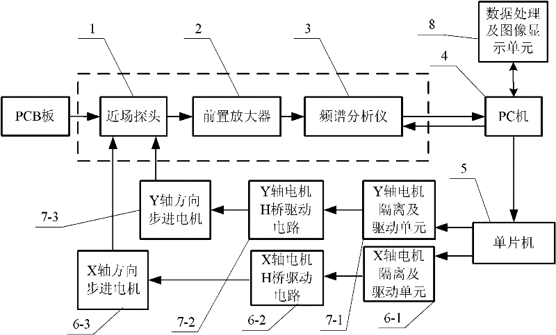
[0043] Specific implementation mode one: the following combination figure 1Describe this embodiment, the device of the qualitative detection PCB board electromagnetic interference radiation performance described in this embodiment, it comprises near-field probe 1, preamplifier 2, spectrum analyzer 3, PC machine 4, single-chip microcomputer circuit 5, X-axis motor Isolation and drive unit 6-1, X-axis motor H-bridge drive circuit 6-2, X-axis direction stepping motor 6-3, Y-axis motor isolation and drive unit 7-1, Y-axis motor H-bridge drive circuit 7-2 and Y-axis direction stepper motor 7-3, PC 4 is embedded with data processing and image display unit 8,
[0044] The mode control signal output end of the PC 4 is connected to the mode control signal input end of the single-chip microcomputer circuit 5, and the X-axis motor control signal output end of the single-chip microcomputer circuit 5 is connected to the control signal input end of the X-axis motor isolation and drive unit ...
specific Embodiment approach 2
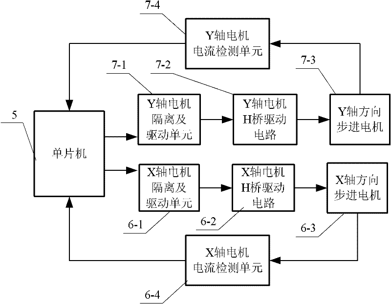
[0051] Specific implementation mode two: the following combination figure 2 Describe this embodiment. The difference between this embodiment and Embodiment 1 is that it also includes a Y-axis motor current detection unit 7-4 and an X-axis motor current detection unit 6-4.
[0052] The Y-axis motor current detection unit 7-4 is used to collect the operating current of the Y-axis direction stepping motor 7-3, and the current signal output end of the Y-axis motor current detection unit 7-4 is connected to the Y-axis motor current signal of the single-chip microcomputer circuit 5 input terminal;
[0053] The X-axis motor current detection unit 6-4 is used to collect the operating current of the stepping motor 6-3 in the X-axis direction, and the current signal output terminal of the X-axis motor current detection unit 6-4 is connected to the X-axis motor current signal of the single-chip microcomputer circuit 5 input. Other components and connections are the same as those in Em...
specific Embodiment approach 3
[0055] Specific implementation mode three: the following combination figure 1 Describe this embodiment, this embodiment is based on the detection method of the device of the qualitative detection PCB board electromagnetic interference radiation performance described in embodiment one, sends the control command of LabVIEW software by PC 4, and single-chip microcomputer circuit 5 according to the control command that receives Determine the scanning mode of the near-field probe 1, and the single-chip microcomputer circuit 5 obtains the movement direction and the movement distance of the stepping motor 6-3 in the X-axis direction and the stepping motor 7-3 in the Y-axis direction according to the received control command, and according to the The movement distance is calculated to obtain the number of driving pulses of the driving signal of the corresponding motor, and then the direction of movement and the number of driving pulses are used to form a control signal for driving the ...
PUM
 Abstract
Description
Claims
Application Information
 - R&D
- Intellectual Property
- Life Sciences
- Materials
- Tech Scout
- Unparalleled Data Quality
- Higher Quality Content
- 60% Fewer Hallucinations
Browse by: Latest US Patents, China's latest patents, Technical Efficacy Thesaurus, Application Domain, Technology Topic, Popular Technical Reports.
© 2025 PatSnap. All rights reserved.Legal|Privacy policy|Modern Slavery Act Transparency Statement|Sitemap|About US| Contact US: help@patsnap.com