
Novel holographic optical tweezers system based on Talbot effect

A new type of holographic technology, applied in the field of laser holographic optical tweezers, can solve the problems of high requirements for operating skills, complex optical trap moving systems, and increase in the cost of holographic optical tweezers systems, and achieve industrialization, cost reduction, and compact and stable systems. Effect

Inactive Publication Date: 2011-08-24
XIAMEN UNIV
View PDF4 Cites 12 Cited by
  • Summary
  • Abstract
  • Description
  • Claims
  • Application Information

AI Technical Summary

Problems solved by technology

In the traditional holographic optical tweezers technology, the holographic optical tweezers using the spatial light modulator has another defect: the manipulation of the trapped particles requires a large number of complex Fourier hologram calculations, so the traditional holographic optical tweezers system often needs to be equipped with High-performance computing equipment, and the complex moving system of the optical trap requires high operating skills, which further increases the cost of the holographic optical tweezers system and limits the popularization and application of the holographic optical tweezers

Method used


Image

  • Novel holographic optical tweezers system based on Talbot effect
  • Novel holographic optical tweezers system based on Talbot effect

Examples


Embodiment 1

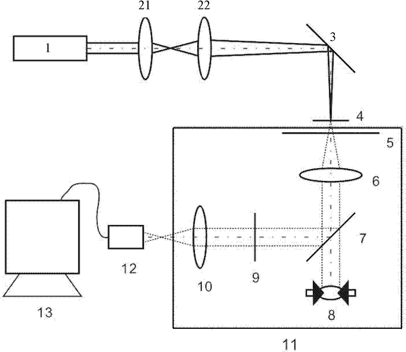
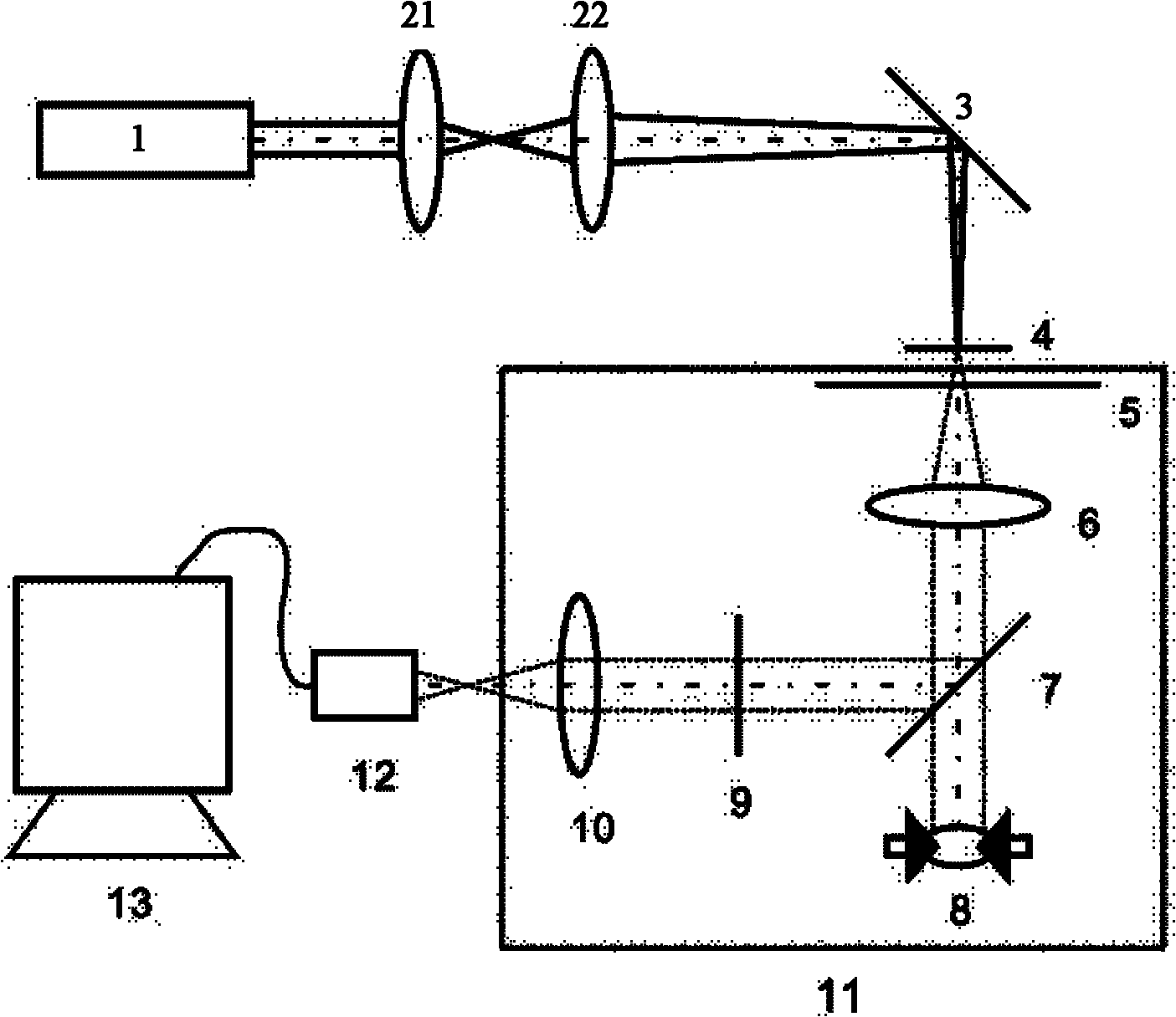
[0014] Such as figure 1 As shown, the embodiment of the present invention is provided with a laser 1, a first lens 21, a second lens 22, a mirror 3, a holographic element 4, an inverted microscope 11, a CCD image sensor 12 and a computer 13; the first lens and the second lens are sequentially The front and back are arranged between the laser beam output end of the laser 1 and the reflector 3, the laser 1, the first lens 21 and the second lens 22 are on the same optical axis, the laser light emitted by the laser 1 passes through the first lens and the second lens, and the first lens The focal point coincides with the initial position of the second lens, and the position of the laser beam focus point is controlled by fine-tuning the distance between the first lens and the second lens, so that the laser beam focus point falls on the holographic element 4; the particles are placed on the inverted microscope On the stage 5 of 11, by adjusting the distance between the stage 5 of the...

Embodiment 2

[0019] Same as Embodiment 1, the difference is that the holographic element 4 is realized by a spatial light modulator, the spatial light modulator is connected to the computer 13, the signal for calculating the hologram is generated by the computer, and the spatial light modulator is controlled by the computer, thereby Change the self-imaging light field distribution of the spatial light modulator, and then manipulate the motion of the particles.


PUM


Abstract

The invention relates to laser holographic optical tweezers, and provides a novel holographic optical tweezers system based on the Talbot effect with a simple structure and high operability. The novel holographic optical tweezers system comprises a laser, a first lens, a second lens, a reflector, a holographic element, an inverted microscope, a CCD image sensor and a computer, wherein the two lens are sequentially arranged between the laser beam output end of the laser and the reflector in tandem; the laser and the two lenses have the same optical axis; the focuses of the two lenses are in coincidence with each other when the two lenses are placed in the initial positions; the focus position of the laser beam can be controlled by micro-adjusting the distance between the two lenses so as to make the focus point of the laser beam located on the holographic element; a particle is placed on the object stage of the inverted microscope; the particle can be arranged in a Talbot self-imaging position of the holographic element by adjusting the distance between the object stage of the inverted microscope and the holographic element; and the information output end of the CCD image sensor isconnected with the computer for image analysis and processing.

Description

technical field [0001] The invention relates to laser holographic optical tweezers, in particular to a novel holographic optical tweezers system based on the Talbot effect. Background technique [0002] Optical tweezers technology is a tool for trapping and manipulating tiny particles using a three-dimensional gradient optical trap formed by the mechanical effect of momentum transfer between light and matter. It plays an extremely important role in the fields of molecular biology, experimental atomic physics, and colloid chemistry. role. As the multi-optical trap manipulation technology becomes more and more important in many experimental researches and applications, optical tweezers have gradually evolved from the original single optical tweezers to various types of multi-optical tweezers, such as dual optical tweezers and scanning optical tweezers. , femtosecond optical tweezers, holographic optical tweezers, etc. Among them, holographic optical tweezers has opened up a ...

Claims


Application Information

Patent Timeline
IPC IPC(8): G02B21/32G21K1/00G02B5/32
Inventor 任雪畅王灿辉刘国华刘守张向苏
Owner XIAMEN UNIV
Learn More