
Automatic debugging system for radio-frequency signal products

A radio frequency signal and automatic debugging technology, which is applied in the transmission system, transmitter monitoring, transmission monitoring, etc., can solve the problems of poor product performance consistency, depending on the length of debugging time, and high requirements for debugging workers, so as to achieve good product performance consistency, The effect of reducing the number of debugging workers and improving production efficiency

Active Publication Date: 2011-08-24
SUMEC MACHINERY & ELECTRIC
View PDF3 Cites 7 Cited by
  • Summary
  • Abstract
  • Description
  • Claims
  • Application Information

AI Technical Summary

Problems solved by technology

[0003] (1) Time-consuming and labor-intensive; manual debugging requires a lot of skilled debugging workers, and the length of debugging time depends on the debugging experience and even luck of the workers;
[0004] (2) Low production efficiency and high rate of defective products: Electronic components produced at home and abroad have precision errors. For radio frequency signals, small precision errors often lead to very large poor performance, which seriously exacerbates the difficulty and persistence of debugging and troubleshooting. time
In the actual situation, many times the manual debugging method of the product cannot reach the standard in a short period of time. At the same time, the manufacturer has to give up debugging in order to increase the output quantity, resulting in a high product defect rate
[0005] (3) Poor product performance consistency: Different debuggers may not have exactly the same judgments and selected debugging methods for the problem, resulting in poor product performance consistency
[0006] (4) High cost: high requirements for commissioning workers, a large number of people, and high precision requirements for components, resulting in high procurement costs

Method used


Image

  • Automatic debugging system for radio-frequency signal products
  • Automatic debugging system for radio-frequency signal products
  • Automatic debugging system for radio-frequency signal products

Examples


Embodiment 2

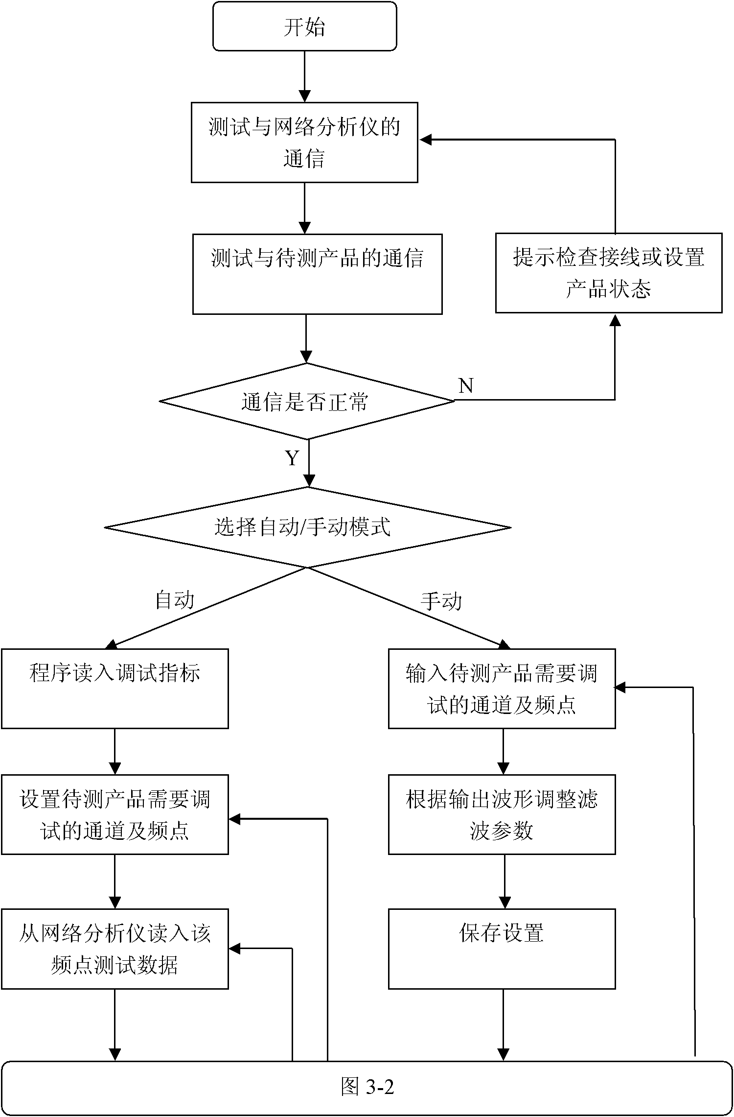
[0047] This embodiment is an automatic debugging method of the radio frequency signal product automatic debugging system in the first embodiment.

[0048] like Figure 3-1 and 3-2 As shown, the PC performs the following steps:

[0049] Step 1 Establish communication between the computer, the vector network analyzer and the product to be tested;

[0050] Step 2 Read in the RF signal channels and channels that need to be debugged this time, and look up the table to preset the frequency point, bandwidth, out-of-band signal suppression and signal gain indicators corresponding to each channel;

[0051] Step 3 Instruct the vector network analyzer to perform the channel performance index test, accept the performance index test data fed back by the vector network analyzer, and judge whether the test data meets the index requirements of the preset table; if it meets the index requirements, perform step 4; if it does not meet the index requirements, go to step 5;

[0052] Step 4 rea...


PUM


Abstract

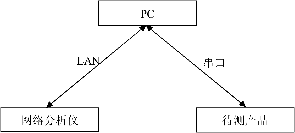
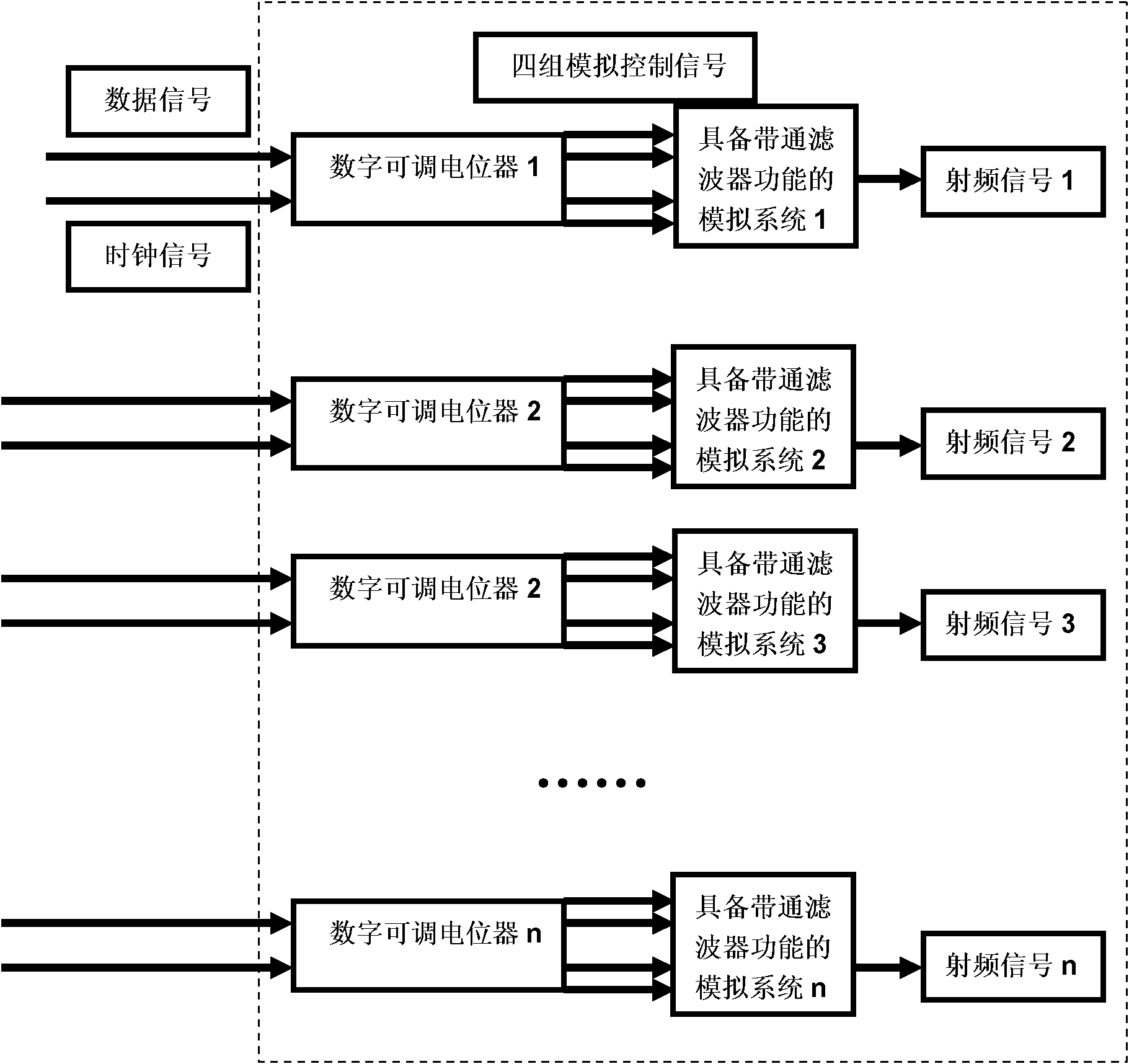
The invention discloses an automatic debugging system for radio-frequency signal products, in which a product to be tested, a vector network analyzer and a computer are arranged, wherein the inside of the computer is provided with a preset table and debugging packets corresponding to each channel, the preset table is used for presetting the frequency point, bandwidth and OOB (out of band) signal curbing and signal gain factor indexes of each corresponding frequency channel within the radio-frequency signal range, and the frequency points in the preset table correspond to the frequency points of all frequency channels to be tested one by one; each channel has n debugging packets, each debugging packet contains groups of debugging control signals which are in a channel and correspond to each frequency channel, each group of debugging control signals refers to four analog voltages, and the four analog voltages are respectively used for debugging the frequency point, bandwidth and OOB (out of band) signal curbing and signal gain factor indexes of the debugging channel; and the computer is connected with the product to be tested by a communication bus, and connected with the vector network analyzer by an LAN line.

Description

technical field [0001] The invention belongs to the field of debugging control of radio frequency signal processing products, and in particular relates to an automatic debugging system of radio frequency signal products. Background technique [0002] At present, in the field of global radio frequency product production, how to quickly and effectively control mass production of radio frequency signal processing products (such as the adjustable bandpass filter in this article) to achieve good debugging results, such as a high proportion of performance standards and consistent products Good sex, etc., has always been an international problem. At present, relevant production and processing enterprises and research institutes at home and abroad all adopt the method of manual debugging: that is, to set performance indicators for the products, and then require the processing workers to use the vector network analyzer to initially test the product performance, and pass the part that...

Claims


Application Information

Patent Timeline
IPC IPC(8): H04B17/00H04B17/11H04B17/21
Inventor 陈超王运良金欣
Owner SUMEC MACHINERY & ELECTRIC
Learn More