Electric polarization controller automatic debugging device and debugging method thereof

A polarization controller and automatic debugging technology, used in instruments, testing optical performance, optics, etc., can solve the problems of low efficiency, manual adjustment of EPC, and high requirements for operators, achieving reduced size, convenient equipment portability, and solving operators. demanding effects

Active Publication Date: 2020-12-18
QUANTUMCTEK
View PDF13 Cites 0 Cited by
  • Summary
  • Abstract
  • Description
  • Claims
  • Application Information

AI Technical Summary

Problems solved by technology

[0005] The technical problem to be solved by the present invention is that in the prior art, EPC debugging requires manual adjustment, high requirements for operators, and low efficiency. An automatic debugging device and a debugging method thereof that can automatically adjust the electric polarization controller are provided

Method used


Image

  • Electric polarization controller automatic debugging device and debugging method thereof
  • Electric polarization controller automatic debugging device and debugging method thereof
  • Electric polarization controller automatic debugging device and debugging method thereof

Examples


Embodiment Construction

[0025] The embodiments of the present invention are described in detail below. This embodiment is implemented on the premise of the technical solution of the present invention, and detailed implementation methods and specific operating procedures are provided, but the protection scope of the present invention is not limited to the following implementation example.

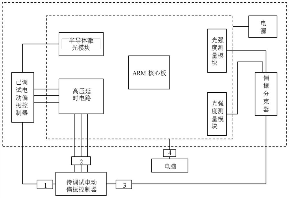
[0026] see figure 2 The automatic debugging device of the electric polarization controller of the present invention includes an ARM core board, a semiconductor laser module, a debugged electric polarization controller, a first light intensity measurement module, a second light intensity measurement module, a high voltage delay circuit, a polarization beam splitter, power supply.

[0027] The semiconductor laser module is connected to the debugged motorized polarization controller to provide light source for the debugged motorized polarization controller.

[0028] The debugged motorized polarization controller is...


PUM


Abstract

The invention provides an electric polarization controller automatic debugging device which comprises a polarization beam splitter, a power supply, a core board, a semiconductor laser module, a debugged electric polarization controller, a high-voltage delay circuit, a first light intensity measurement module and a second light intensity measurement module. The semiconductor laser module is connected to the debugged electric polarization controller, the debugged electric polarization controller is connected to the EPC to be debugged, the EPC to be debugged is connected to the polarization beamsplitter at the same time, the polarization beam splitter is connected with the first light intensity measurement module and the second light intensity measurement module, and the high-voltage delay circuit is connected between the debugged electric polarization controller and the EPC to be debugged. The semiconductor laser module, the high-voltage delay circuit, the first light intensity measurement module and the second light intensity measurement module are connected to the core board, and the power supply is used for supplying power. The invention further provides an electric polarizationcontroller automatic debugging method. The device has the advantages that automatic debugging is achieved, and the defects that manual adjustment has high requirements for operators, time is wasted inoperation and efficiency is low are overcome.

Description

technical field [0001] The invention belongs to the technical field of polarization controller debugging, and in particular relates to an automatic debugging device and a debugging method for a motorized polarization controller. Background technique [0002] Polarization controller (PC): refers to a device that can transform any input polarization state into any desired output polarization state; polarization controllers are widely used in coherent optical fiber communication systems and other coherent measurement systems in the field of quantum communications. The electric polarization controller (EPC) is a fiber extrusion type polarization controller, which is an important type of polarization controller. It mainly squeezes the optical fiber through the thrust of the deformation of the piezoelectric ceramic PZT after it is energized, and produces a stress birefringence effect to change The polarization state has the advantages of simple structure and fast response time. ...

Claims


Application Information

Patent Timeline
Patent Type & Authority Applications(China)
IPC IPC(8): G01M11/02G02F1/01
CPCG01M11/02G02F1/0136
Inventor 胡浩徐炎丁传杨郑伯然郭俊
Owner QUANTUMCTEK
Why Eureka
Try Eureka