

Combustor and gas turbine with same
一种燃烧器、燃烧区域的技术,应用在燃烧设备、燃烧室、燃烧方法等方向,能够解决制造成本增大、大空间、维护作业繁杂等问题,达到提高维护性、削减空间的效果
- Summary
- Abstract
- Description
- Claims
- Application Information
AI Technical Summary
Problems solved by technology
Method used
Image

Examples
no. 1 approach
[0054] refer to Figure 1 to Figure 4 , the gas turbine 1 according to the first embodiment of the present invention will be described.
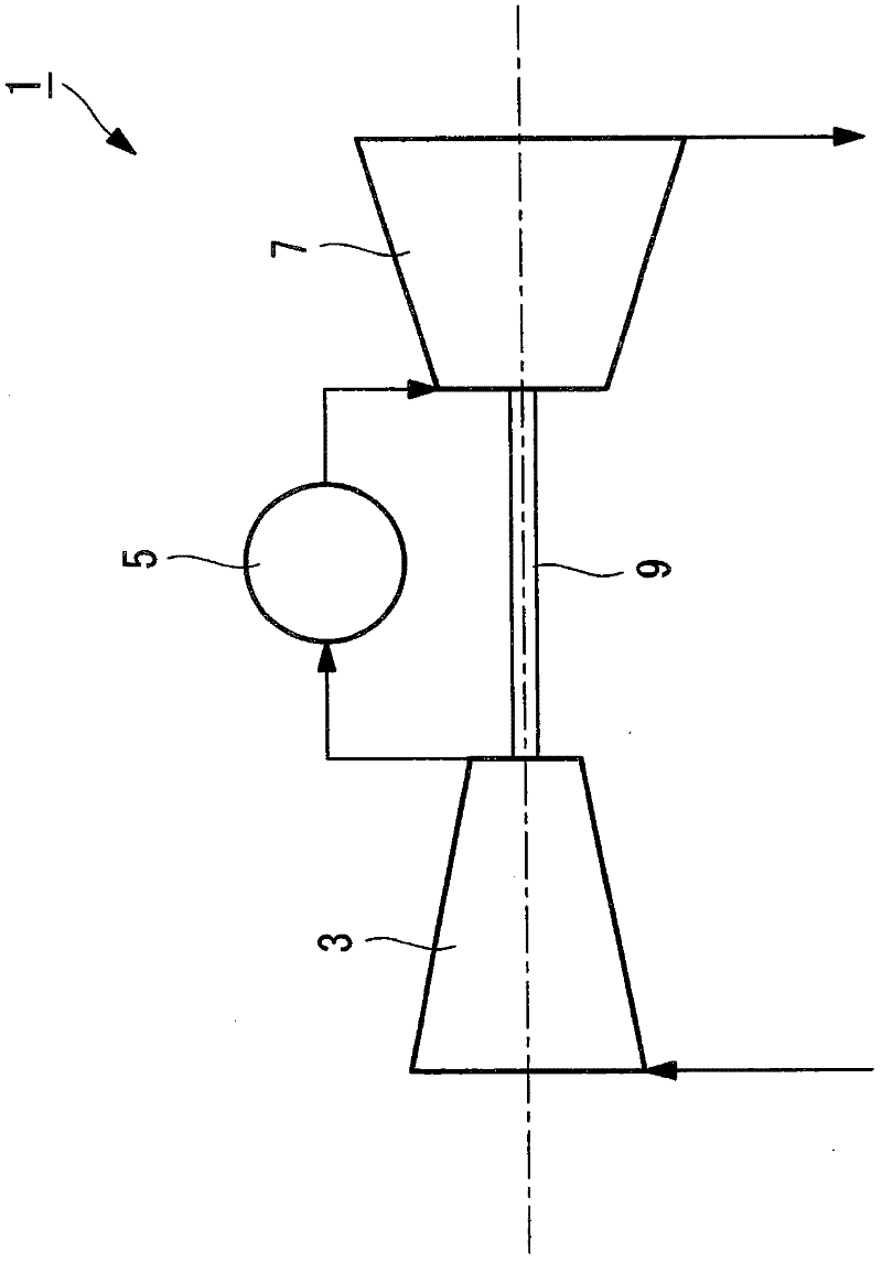
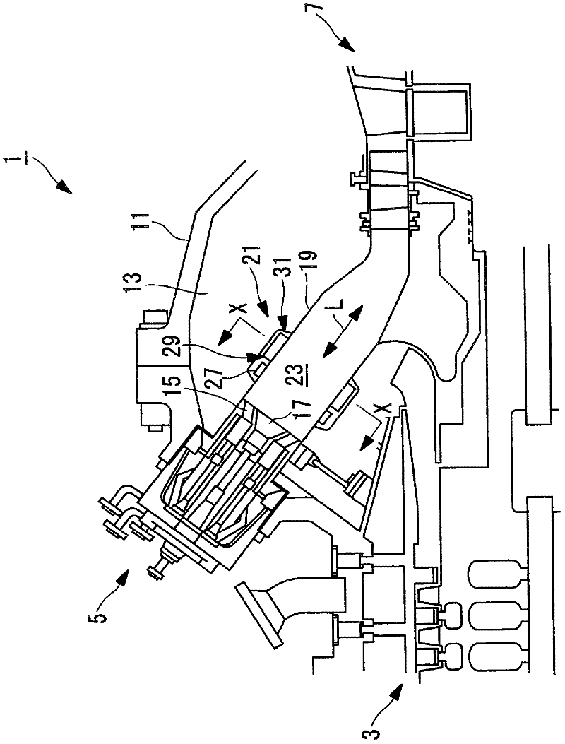
[0055] figure 1 It is a schematic diagram explaining the structure of the gas turbine 1 of this embodiment. figure 2 is description figure 1 A schematic diagram of the outline of the structure of the burner 5.
[0056] Such as figure 1 and figure 2As shown, the gas turbine 1 includes a compressor 3 , a combustor 5 , a turbine unit (turbine) 7 , a rotating shaft 9 , and a housing 11 for holding them at predetermined positions inside.
[0057] The compressor 3 takes in and compresses external air, that is, the atmosphere, and supplies the compressed air to the combustor 5 .
[0058] In addition, as the compressor 3, a well-known structure can be used, Especially the structure is not limited.
[0059] Such as figure 1 As shown, the combustor 5 mixes the air compressed by the compressor 3 and the fuel supplied from the outside, and com...
no. 2 approach 〕
[0126] Next, refer to Figure 6 and Figure 7 A second embodiment of the present invention will be described.
[0127] The basic structure of the gas turbine of this embodiment is the same as that of the first embodiment, but the structure of the damping device 21 is different from the first embodiment. Therefore, in the present embodiment, the different attenuating devices 21 will be mainly described, and redundant descriptions of other components and the like will be omitted.
[0128] Figure 6 It is a cross-sectional view of main parts illustrating the structure of the damper 21 in the combustor 5 of the gas turbine 1 according to the present embodiment. Figure 7 yes Figure 6 The Z-Z section view.
[0129] In addition, the same code|symbol is attached|subjected to the same component as 1st Embodiment, and the description is abbreviate|omitted.
[0130] In the present embodiment, the muffler cover (acoustic portion) 53 is a box having a substantially rectangular cros...
no. 3 approach 〕
[0148] Next, refer to Figure 8 and Figure 9 A third embodiment of the present invention will be described.
[0149] The basic structure of the gas turbine of this embodiment is the same as that of the first embodiment, but the structure of the damping device 21 is different from the first embodiment. Therefore, in this embodiment, different attenuation devices 21 will be mainly described, and redundant descriptions of other components and the like will be omitted.
[0150] Figure 8 It is a cross-sectional view of main parts illustrating the structure of the damping device 21 of the combustor 5 of the gas turbine 1 according to the present embodiment. Figure 9 yes Figure 8 The W-W section view.
[0151] In addition, the same code|symbol is attached|subjected to the same component as 1st Embodiment, and the description is abbreviate|omitted.
[0152] The muffler 31 includes a muffler cover (acoustic part) 61 and an opening 63 provided in the liner cover 35 .
[0153]...
PUM
 Abstract
Description
Claims
Application Information