
Efficient sieve plate carbonating tower with liquid phase as continuous phase

A technology of carbonation tower and sieve plate, which is applied in the direction of chemical method for reacting liquid and gas medium, carbonate preparation, chemical instrument and method, etc., and can solve the problem that high-efficiency trays are not applicable and easy to accumulate crystallization and scarring , tower fluid axial back-mixing and other issues, to achieve light weight, simple structure, and solve the effect of axial back-mixing

Inactive Publication Date: 2011-08-31
CHINA CHENGDA ENG
View PDF4 Cites 2 Cited by
  • Summary
  • Abstract
  • Description
  • Claims
  • Application Information

AI Technical Summary

Problems solved by technology

In 2004, Dalian Chemical Industry Research and Design Institute applied for the patent for the invention of the multi-stage sieve tray inner circulation carbonization tower. There are still bacterial caps on the sieve plate, which is an improved bacterial cap tray with a relatively complicated structure.
In 2006, Tianjin Bohai Chemical Co., Ltd. applied for the invention patent of the sieve plate carbonization tower. The sieve plate aperture of the tower is 30-110mm, and the opening rate is 6-20%. There is no downcomer, which is a high opening rate, and the gas-liquid mixed flow structure, there is still the disadvantage of axial back-mixing of tower liquid
In the soda production, the carbonation tower not only uses the liquid phase as the continuous phase, but also has a supersaturated solution with a large number of solid crystals suspended in the tower, and it is easy to accumulate crystals on the tray and cause scarring, so the high efficiency of general chemical engineering Trays are not applicable

Method used


Image

  • Efficient sieve plate carbonating tower with liquid phase as continuous phase
  • Efficient sieve plate carbonating tower with liquid phase as continuous phase

Examples


Embodiment 1

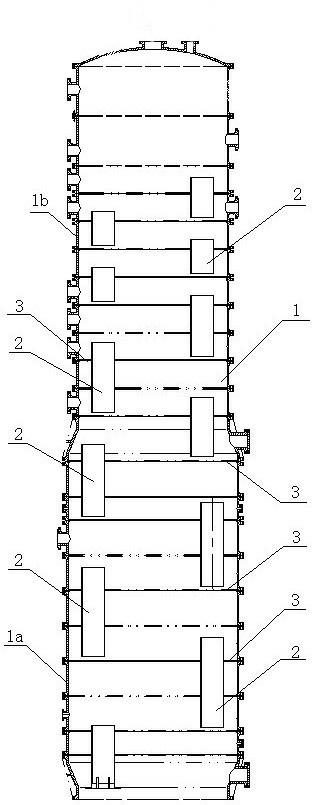
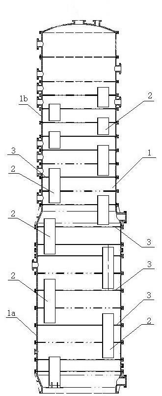
[0021] Embodiment 1: A high-efficiency sieve plate carbonation tower with the liquid phase as the continuous phase, comprising a tower body 1, a liquid inlet and a gas outlet are arranged at the top of the tower body 1, and in the tower body 1, from top to There are several sieve plates 3 with low opening ratios provided with downcomers 2. The sieve plates 3 have a porosity rate of 0.3-2.5%. There is a certain gap between two adjacent sieve plates. The diameter of the sieve hole on the plate 3 is 10-30mm; since the gas composition and volume in the tower are in the process of changing, the opening ratio, sieve hole diameter and sieve hole diameter of the sieve plate 3 from top to bottom in the tower body 1 The number is variable, wherein the two downcomers 2 are located at the edge of the sieve plate 3 .

Embodiment 2

[0022] Embodiment 2: in ammonia alkali method alkali making, such as figure 1 As shown, a high-efficiency sieve plate carbonation tower with the liquid phase as the continuous phase includes a tower body 1, and a liquid inlet and a gas outlet are arranged on the top of the tower body 1. The tower body 1 is a different-diameter tower body. The diameter of the middle part 1a of the body is 3400mm, and the diameter of the upper part 1b of the tower body is 3000mm; in the tower body 1, 12 low-opening sieve plates 3 with two downcomers 2 are arranged from top to bottom, The opening ratio of the sieve plate 3 is 1.2-2.2%, there is a certain gap between two adjacent sieve plates, and the diameter of the sieve hole on the sieve plate 3 is 16-30mm, because the gas composition and volume in the tower are different In the process of changing, the opening rate, sieve hole diameter and sieve hole number of the sieve plate 3 from top to bottom in the tower body 1 change, and its opening rat...

Embodiment 3

[0024] Embodiment 3: In the soda production by combined alkali method, a kind of high-efficiency sieve plate carbonation tower with liquid phase as the continuous phase comprises a tower body 1, and a liquid inlet and a gas outlet are arranged at the top of the tower body 1, and the tower body 1 is a different-diameter tower body, the diameter of the middle part of the tower body is 2800mm, and the diameter of the upper part of the tower is 2500mm. In the tower body 1, there are 13 low openings with two downcomers 2 from top to bottom. rate sieve plate 3, the opening rate of the sieve plate 3 is 0.3-0.8%, there is a certain gap between two adjacent sieve plates, and the diameter of the sieve hole on the sieve plate 3 is 10-16mm, due to the The gas composition and volume are all in the process of changing. The opening ratio, diameter and number of sieve holes of the sieve plate 3 from top to bottom in the tower body 1 change, and the opening ratio and sieve diameter are within t...


PUM

PropertyMeasurementUnit
Diameteraaaaaaaaaa
Diameteraaaaaaaaaa
Diameteraaaaaaaaaa

Abstract

The invention discloses an efficient sieve plate carbonating tower with a liquid phase as a continuous phase, which comprises a tower body; a plurality of low-opening-rate sieve plates with downcomers are arranged in the tower body from top to bottom; the opening rate of the sieve plates is 0.3-2.5 percent; and a certain gap is left between two adjacent sieve plates. The low-opening-rate sieve plates with the downcomers are arranged in the tower body, so that a layer of air cushion can be formed below the sieve plates, the problem of axial backmixing of the liquid among the sieve plates is solved, and the absorption efficiency of the sieve plates is improved; because the composition and the volume of the gas in the tower are both in a changing process, the diameters, the number and the opening rate of sieve pores of the sieve plates in the tower change; through model observation, under the condition that the tower body is filled with liquid, the sieve plates arranged correspondingly arranged according to the change of the composition and the volume of the gas in the tower are more beneficial to improving the efficiency of absorbing the gas in the tower by the sieve plates; and through the arrangement of at least two downcomers on each sieve plate, the liquid can be uniformly distributed on the next layer of the sieve plate after passing through the sieve plate.

Description

technical field [0001] The invention relates to a high-efficiency sieve plate carbonation tower with liquid phase as continuous phase. Background technique [0002] The carbonation reaction is a slow chemical reaction, so the reaction equipment is required to have sufficient liquid phase residence time. Historically, the carbonation tower is filled with liquid, and the liquid phase is the continuous phase, which can increase the liquid residence time in the tower and fully Complete the chemical reaction. [0003] The traditional carbonation towers all use cap trays, which are bubbling trays with the liquid phase as the continuous phase, and are cast with cast iron. However, since the gas and liquid phases mix and flow up and down in the same channel, there are inevitably serious problems. The tower liquid is axially back-mixed, thereby reducing the efficiency of the tray, reducing the production intensity of the tower, and reducing CO 2 absorption efficiency, resulting in ...

Claims


Application Information

Patent Timeline
IPC IPC(8): B01J10/00C01D7/18
Inventor 周光耀黄建华薛霜周永华
Owner CHINA CHENGDA ENG
Features
  • Generate Ideas
  • Intellectual Property
  • Life Sciences
  • Materials
  • Tech Scout
  • Unparalleled Data Quality
  • Higher Quality Content
  • 60% Fewer Hallucinations
Learn More