Labeler and a labeling method for labeling plastic bottles in a blow mold

一种贴标签机、吹塑模具的技术,应用在贴标签、标签、运输和包装等方向,能够解决不适瓶子设计、限制印刷质量、不利等问题,达到快速移动、避免过度拉伸、高可靠性的效果

Inactive Publication Date: 2011-08-31
KRONES AG
View PDF14 Cites 1 Cited by
  • Summary
  • Abstract
  • Description
  • Claims
  • Application Information

AI Technical Summary

Problems solved by technology

However, this technical solution is also not suitable for various bottle designs
It is also disadvantageous in terms of requiring at least one print head per blow mold, limiting print quality and / or print style, and having to handle coloring on the blow molding machine

Method used


Image

  • Labeler and a labeling method for labeling plastic bottles in a blow mold
  • Labeler and a labeling method for labeling plastic bottles in a blow mold
  • Labeler and a labeling method for labeling plastic bottles in a blow mold

Examples


Embodiment Construction

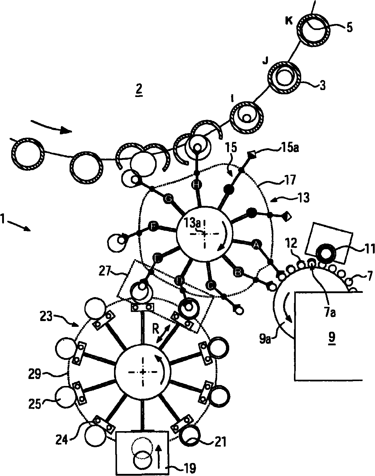
[0031] if possible from figure 1 It is seen that a first embodiment of a labeling machine 1 comprises a blowing wheel 2 with a plurality of blow molds 3 for producing labeled bottles 5 or other plastic containers from preforms 7 . The preform 7 is heated in an oven 9 in a known manner, glue 12 is then applied tangentially to the circumferential section 7a of said preform 7 by means of a glue roller 11, and the preform 7 is formed, for example, by a joint Received from transfer starwheel 13 from adaptive starwheel or the like. On the circumference of said transfer star wheel 13 are arranged a rotatably supported clamping arm 15 and a first control cam 17, the clamping arm 15 being of variable length and equipped with a clamping element 15a for the preform 7, the first A control cam 17 is used for controlling the clamping arm 15 , in particular for adjusting the radial position and orbital speed of the clamping arm 15 .

[0032] Furthermore, at least one label dispenser 19 suc...


PUM


Abstract

The invention relates to a labeler and a labeling method for labeling plastic bottles in a blow mold. A labeler for labeling plastic bottles in the blow mold, in particular in the rotary blow molder comprising a plurality of blow molds; a transfer star wheel for introducing preforms into the blow molds; and at least one transfer device for transferring labels to the preforms, and the transfer star wheel and the transfer device move the preforms and the labels towards one another in a transfer region in such a way that a respective label is affixed to a circumferential subarea of a preform. In this manner, the label can be inserted in the blow mold in a particularly fast and reliable manner and excessive stretching of the label during blow molding can be avoided.

Description

technical field [0001] The invention relates to a labeling machine for in-mold labeling of plastic bottles according to the preamble of claim 1 and a labeling method according to claim 11 using a labeling machine according to the invention. Background technique [0002] As is well known, plastic bottles can already be labeled during the production process by introducing the label into the blow mould, via so-called in-mold labeling (IML), before blow molding is performed. To this end, the labels are positioned by means of clamps on the inner wall of the open blow mould, as described in US6649119B2, US5266149A and WO0078526A1 concerning rotary blow molding machines. However, a transfer star with clips is technically complex. A non-rotating, timed transfer system does not achieve the desired manufacturing efficiencies. In addition, there is a need for a device that can be easily integrated into existing blow molding machines so as to take up very little space. [0003] Thus,...

Claims


Application Information

Patent Timeline
Patent Type & Authority Applications(China)
IPC IPC(8): B29C49/24B65C3/26
CPCB29C2049/2449B29C2049/021B29C49/02B29C2049/2433B29B2911/14313B65C3/00B29C2049/2422B29C2049/2443B29C49/2408B29C49/36B29C2049/2412B29C49/24B29C2949/3092B29C2949/08
Inventor 沃尔夫冈·豪斯拉登克里斯帝安·波普维尔纳·布里顿
Owner KRONES AG
Why Eureka
Try Eureka