Oscillatory type tidal power generation device

A tidal current power generation and oscillating technology, which is applied in ocean energy power generation, engine components, machines/engines, etc., can solve the problems that tidal current oscillating power generation technology has not yet made actual progress, and achieve simple structure, high reliability and low failure rate Effect

Inactive Publication Date: 2011-08-31
SHANDONG UNIV
View PDF6 Cites 21 Cited by
  • Summary
  • Abstract
  • Description
  • Claims
  • Application Information

AI Technical Summary

Problems solved by technology

It is a trend to develop tidal current oscillation power generation technology suitable for low-velocity and sh

Method used


Image

  • Oscillatory type tidal power generation device
  • Oscillatory type tidal power generation device
  • Oscillatory type tidal power generation device

Examples


Embodiment 1

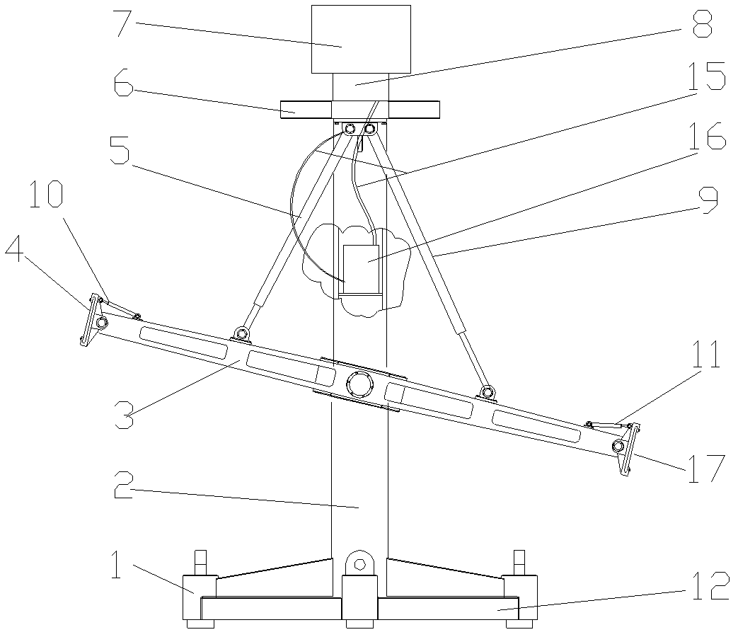
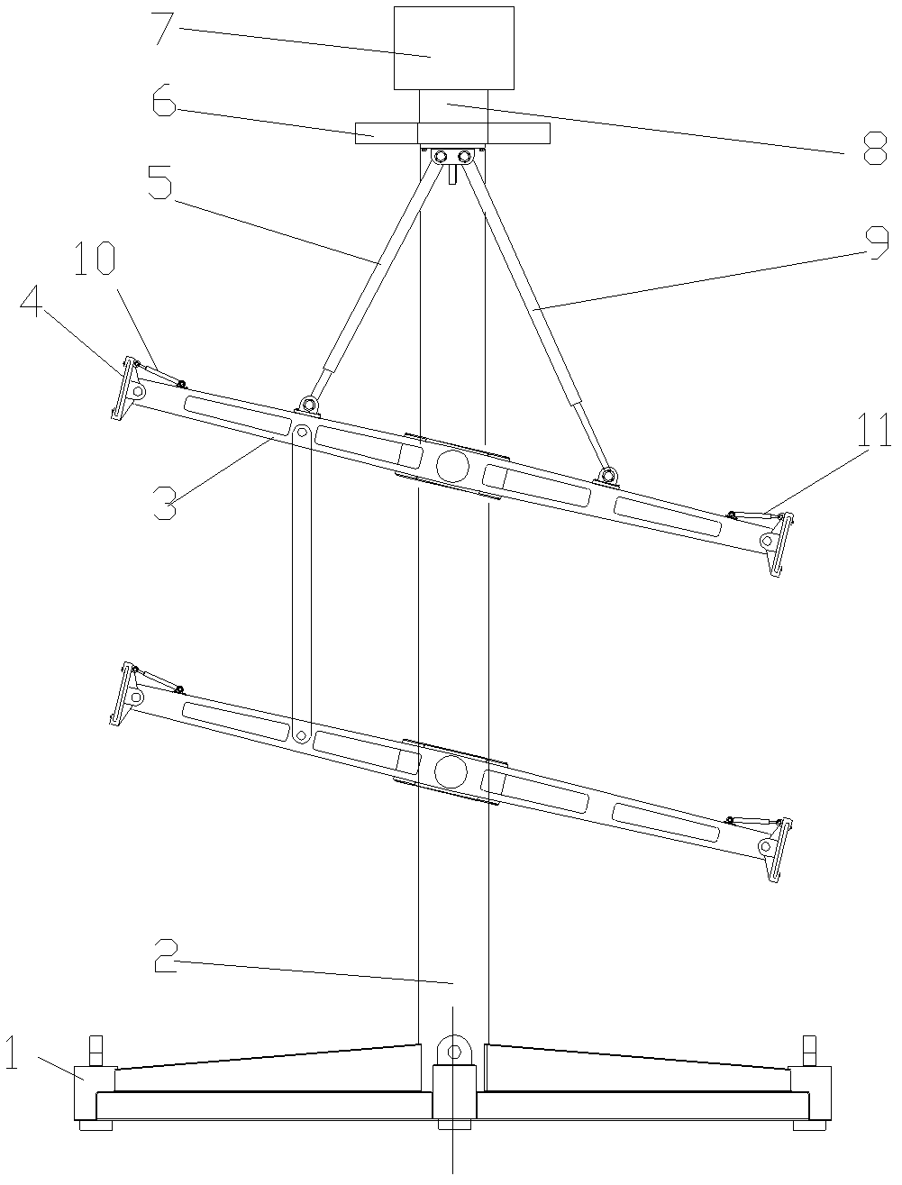
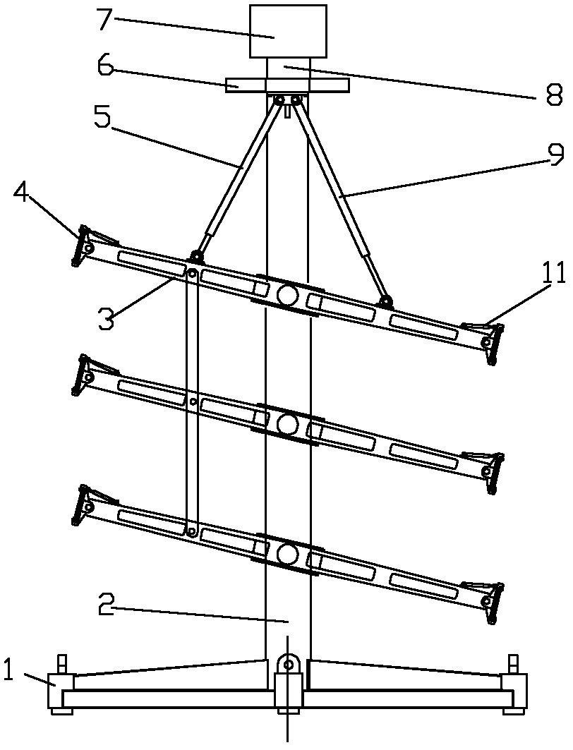
[0022] Such as figure 1 As shown, the oscillating tidal current power generation device of the present invention includes a base 12, a base adjustment cylinder 1, a column 2, a tidal current energy absorbing plate 4, a hydraulic accumulator 16, a power generation cylinder 5, a generator 7, a power generation hydraulic motor 8, a power generation Oil cylinder 9 and energy-absorbing plate angle adjustment oil cylinder 10. The column 2 is installed on the base 12, and the base 12 is equipped with at least one vertically placed base adjustment oil cylinder 1 ( figure 1 There are four in the middle), and the adjustment of the base adjustment oil cylinder 1 ensures that the column 2 stands vertically on the seabed. At least one swing arm 3 is installed on the column 2, the middle part of the swing arm 3 is hinged with the column 2 through a rotating shaft, and the swing arm 3 can swing around the rotating shaft. When there are two or more swing arms 3, each swing arm 3 is connecte...

Embodiment 2

[0026] Such as Figure 4 As shown, this embodiment is to figure 1 The power generation cylinder 5 and the power generation cylinder 9 in the given embodiment 1 are replaced by a swing cylinder 14, and the tidal current energy absorbing plate 4 and the tidal current energy absorbing plate 17 at both ends of the swing arm 3 are installed on the swinging cylinder 13 and the swinging cylinder 18 respectively. both ends of arm 3.

[0027] The tidal current energy-absorbing plate 4 and the tidal current energy-absorbing plate 17 oscillate up and down while compressing the swing oil cylinder 14 to output high-pressure oil. Swing oil cylinder 14 can be sealed in the column 2, is not corroded by sea water.

[0028] Compared with the impeller energy-absorbing technology, the size of the energy-absorbing plates 4 and 17 of the oscillating tidal current energy-absorbing device of the present invention is not limited in the horizontal direction; in the vertical direction, as the water de...


PUM


Abstract

The invention provides an oscillatory type tidal power generation device which comprises a base, a column, tidal energy-absorbing boards, a power generation oil cylinder, a hydraulic power accumulator, a generator and a power generation hydraulic motor, wherein the column is arranged on the base and at least one swing arm is arranged on the column; the power generation oil cylinder is connected between the swing arm and the column; the tidal energy-absorbing boards are respectively arranged at the two ends of the swing arm; the power generation oil cylinder is connected with the hydraulic power accumulator which is arranged on the column through an oil pipe; the hydraulic power accumulator is connected with the power generation hydraulic motor through an oil pipe; the power generation hydraulic motor, the hydraulic power accumulator and the generator are all arranged on the column; and the power generation hydraulic motor is connected with the generator. According to the invention, a tide-driven hydraulic device is used to drive mechanical energy into electric energy; high-pressure hydraulic oil produced by the oscillation of the tidal energy-absorbing boards can drive the generator to generate electricity by the rotating of the power generation hydraulic motor. The device has simple structure, high reliability, low failure rate and is easy to install and maintain. Not only is the device suitable for high current sea areas, but also suitable for slow flow areas with lower flow rate and shallow sea areas.

Description

technical field [0001] The invention relates to a power generation device suitable for ocean tidal current power generation, which belongs to the technical field of power generation. Background technique [0002] With the rapid development of the economy, the consumption of resources has increased sharply, and the contradiction between energy supply and demand has become increasingly prominent. Fossil fuel resources are limited, and the consumption of more fossil fuels will inevitably cause more serious environmental pollution. The ocean area accounts for 71% of the total area of ​​the earth. Most of the energy from the sun reaching the earth falls on the sky above the ocean and in the seawater. Part of the energy is attached to the seawater in the form of waves, currents, tides, and temperature differences through various physical or chemical processes. The available energy in ocean energy greatly exceeds the sum of the current global energy demand, and it is a clean and r...

Claims


Application Information

Patent Timeline
IPC IPC(8): F03B13/26
CPCY02E10/38Y02E10/30
Inventor 王勇谢玉东
Owner SHANDONG UNIV
Why Eureka
Try Eureka