Method for comprehensively measuring reflectivity

A comprehensive measurement and reflectivity technology, which is applied in the direction of reflective surface testing, scattering characteristic measurement, optical performance testing, etc., can solve the problems of inaccurate measurement and inaccurate measurement of reflectivity, etc., and achieve the effect of simple and convenient switching

Inactive Publication Date: 2011-08-31
INST OF OPTICS & ELECTRONICS - CHINESE ACAD OF SCI
View PDF8 Cites 38 Cited by
  • Summary
  • Abstract
  • Description
  • Claims
  • Application Information

AI Technical Summary

Problems solved by technology

[0004] The above-mentioned spectrophotometric device cannot accurately measure the reflectivity of optical elements with a reflectivity higher than 99.9%, and the high reflectivity measurement device based on optical cavity ring-down technology cannot measure the reflectivity of the optical element to be meas

Method used


Image

  • Method for comprehensively measuring reflectivity
  • Method for comprehensively measuring reflectivity
  • Method for comprehensively measuring reflectivity

Examples


Embodiment Construction

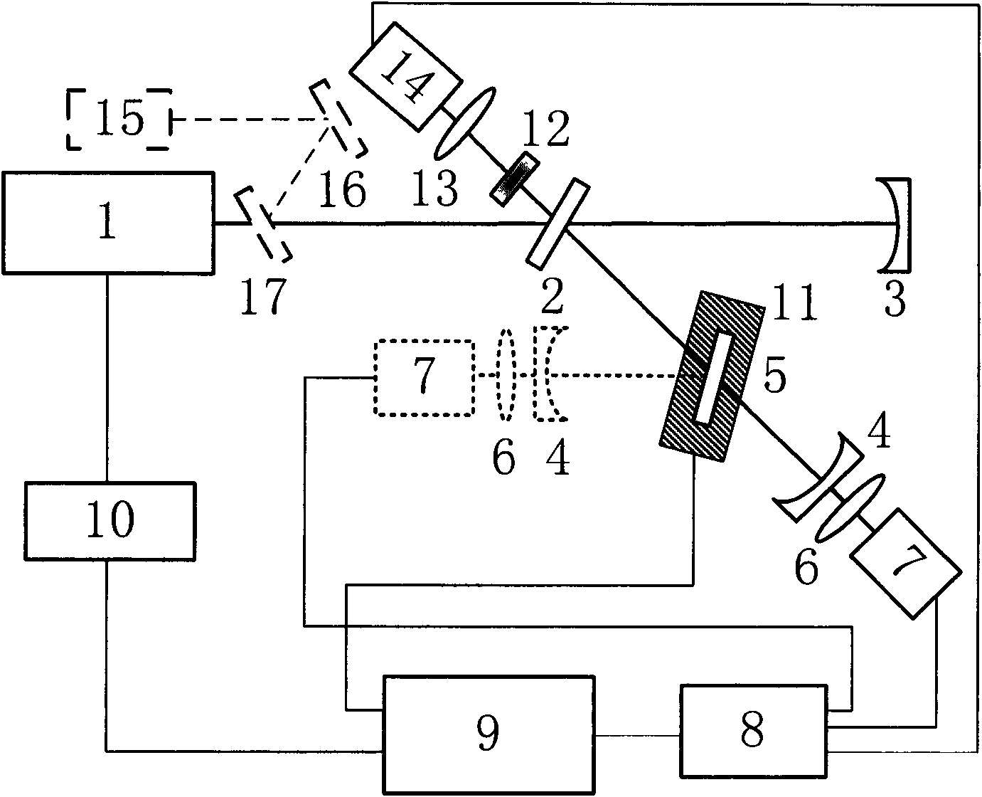
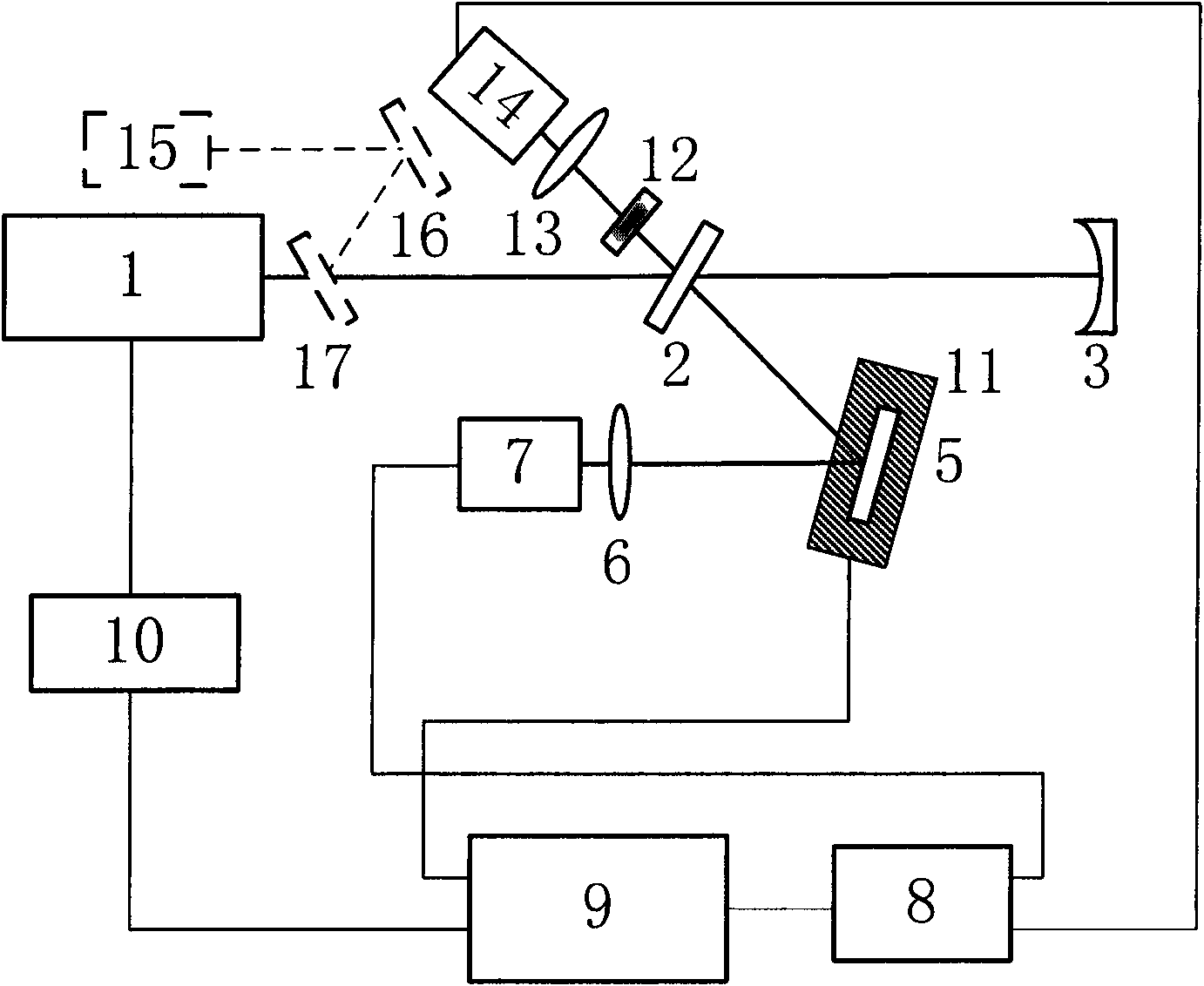
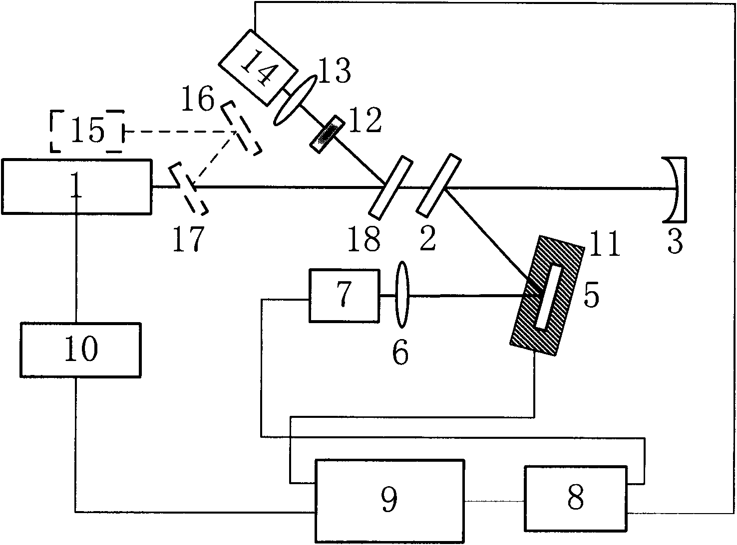
[0028] Attached below figure 1 The system described describes an integrated reflectance measurement device of the present invention. figure 1 Middle: 1 is the light source, 2 is the plane high reflection mirror, 3 and 4 are the plano-concave high reflection mirror, 5 is the optical element to be tested, 6 and 13 are the focusing lens, 7 and 14 are the photodetector, 8 is the data acquisition card , 9 is a computer, 10 is a function card, 11 is a two-dimensional displacement platform, 12 is a variable attenuator, 15 is a visible auxiliary light source, 16 is a reflector, 17 is a beam splitter, and the plano-concave high reflector 4 is a flat The concave high reflection output cavity mirror, the thick line in the figure is the optical path, and the thin line is the connecting line.

[0029] The light source 1 is a continuous semiconductor laser, the laser adopts square wave modulation output, and the square wave is generated by the function generation card 10 controlled by the ...


PUM


Abstract

The invention relates to a method for comprehensively measuring reflectivity, which comprises the following steps: dividing continuous incident laser beams into a reference beam and a detection beam, wherein the reference beam is focused on a photoelectric detector for direct detection and the detection beam is injected into an optical resonant cavity; using a cavity ring-down technology to measure an optical element with reflectivity more than 99%, respectively measuring a ring-down time tau 0 of an original optical resonant cavity output signal and a ring-down time tau 1 of the measured optical resonant cavity output signal after an optical element to be measured is added, and calculating the reflectivity R of the optical element to be measured; using the spectrophotometry to measure the reflectivity of the optical element to be measured when the R value is less than 99%; moving away an output cavity mirror; focusing detecting light reflected by a measuring mirror on the photoelectric detector for detecting while recording a light intensity signal ratio of the detection beam to the reference beam; and calibrating to further obtain the reflectivity R of the optical element to be measured. The device for measuring reflectivity can be used for measuring optical elements with any reflectivity and also can be used for realizing the high-resolution two-dimensional imaging of the reflectivity distribution of a large-aperture optical element.

Description

technical field [0001] The invention relates to a method for comprehensively measuring the reflectivity of optical elements, in particular to a method for measuring the reflectivity of arbitrary reflectivity optical elements and large-diameter optical elements. Background technique [0002] Spectrophotometry is the most commonly used method for measuring the transmittance and reflectance of optical components. In principle, as long as the reflected light energy flow E r and the incident light energy flow E 1 , the reflectivity is R=E r / E 1 . In actual measurement, the fluctuation of the output power of the laser light source is an important factor affecting the measurement results. For some high-reflectance optical components with a reflectivity of over 99.9%, the light intensity is very close when the optical component is not added to the optical path and when the optical component is added to the optical path. At this time, the slight fluctuation of the output power o...

Claims


Application Information

Patent Timeline
IPC IPC(8): G01M11/02
CPCG01N21/55G01M11/005H01S3/0014
Inventor 李斌成曲哲超韩艳玲
Owner INST OF OPTICS & ELECTRONICS - CHINESE ACAD OF SCI
Why Eureka
Try Eureka