
Method for filing and displaying coupling screwed torsion graph in real time

A real-time display and graphics technology, applied in the direction of comprehensive factory control, comprehensive factory control, electrical program control, etc., can solve the problems of slow display of trend control, scattered data, inconvenient use, etc., to facilitate backup and transfer, and improve screwing efficiency , Ease of production management

Active Publication Date: 2013-02-20
洛阳锐腾机械设备有限公司
View PDF0 Cites 0 Cited by
  • Summary
  • Abstract
  • Description
  • Claims
  • Application Information

AI Technical Summary

Problems solved by technology

But as far as the real-time display of torque graphics is concerned, first, the trend control in WINCC can only display the curve of the process variable value changing with time, such as the curve of torque changing with time and the number of turns changing with time, but cannot display two process variables Second, when the data sampling frequency is high, the trend control in WINCC will display slowly, and the complete curve will not be displayed on the screen until several seconds after the screwing is completed.
As far as the data storage of torque and turns during the screwing process is concerned, the data archiving of WINCC is to save each single process variable in the SQL Server database in chronological order, and the data is dispersed. In order to subsequently separate the data of each pipe, it needs to be recorded The start time and end time of each pipe, and then search in the archived data to generate a report, the process is cumbersome and inconvenient to use

Method used


Image

  • Method for filing and displaying coupling screwed torsion graph in real time

Examples


Embodiment Construction

[0010] The present invention is described in conjunction with accompanying drawing and embodiment:

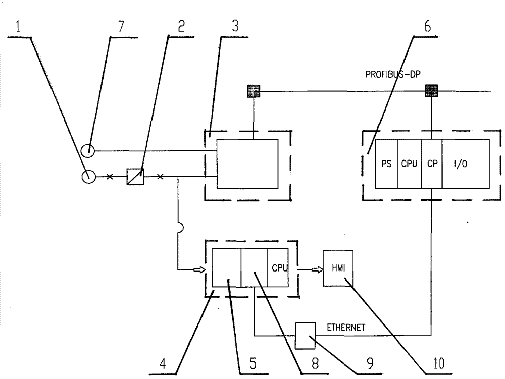
[0011] Such as figure 1 As shown, a method for real-time display and archiving of coupling torque graphics, force sensor 1 (model such as Z7AD1 / 10T of HBM Company) and transmitter 2 (model such as AE301 of HBM Company) located on the screwing machine Connection, the physical signal size of the force sensor in this embodiment is 2mv / v, the physical signal of the force sensor is converted into a standard analog signal (±10v in this example) through the transmitter 2, and the standard analog signal enters the scene PLC 3 (model such as ET200 of Siemens Company), the other is connected to the high-speed data acquisition card 5 (model such as PCI-8310) in the PCI slot of the industrial computer 4 (model such as MEC-9002 of EVOC); The analog signal is transmitted to the main PLC 6 (model such as S7-315DP2 of Siemens) through the PROFIBUS-DP network, and becomes a digital quantity th...


PUM


Abstract

The invention relates to a method for filing and displaying a coupling screwed torsion graph in real time. The method comprises the following steps: converting a physical signal of a force sensor (1) into a standard analog signal through a converter (2), and then sending one path of standard analog signal into an on-site PLC (programmable logic controller) (3) while switching the other path of standard analog signal into a high-speed data acquisition card (5) of an industrial personal computer; transmitting the standard analog signal which is switched into the PLC (3) into a master PLC (6) through a network, performing the analog-to-digital conversion and calibration on the standard analog signal, and then generating a torsion value for controlling a main screwed torsion; generating a pulse signal by a rotary encoder (7), transmitting the pulse signal to the master PLC (6) through the PLC (3) and the network, and then converting the pulse signal into a real-time circle value by a FM (frequency modulation) module and finally outputting; performing the analog-to-digital conversion and digital quantity operation on the standard analog signal which is switched into the high-speed data acquisition card (5) so as to obtain the torsion value while acquiring the real-time circle value from the master PLC (6); and drawing a variation trend graph of the torsion following the change of circle number on a HMI (human machine interface) (10), and storing the tube basic data and process data.

Description

technical field [0001] The invention belongs to the technical field of automation control, and relates to a method for real-time display and archiving of coupling torque graphics, which is mainly used in an automatic control system of a twisting device of a coupling twisting machine in the production of seamless steel pipes in the petroleum industry. Background technique [0002] Usually, the seamless steel pipe used in the oil field is screwed on one end of the steel pipe with a coupling before leaving the factory, and the other end is only provided with a protective sleeve for the thread. When drilling wells in the oil field, screw the thread at one end of the protective sleeve into the coupling of the upper steel pipe. Connect them in turn to form an oil well; the coupling is to connect a long steel pipe with corresponding external threads at both ends and a steel pipe with internal threads at both ends. Connected, the two ends of the car have shorter internal threads, an...

Claims


Application Information

Patent Timeline
Patent Type & Authority Patents(China)
IPC IPC(8): G05B19/418
CPCY02P90/02
Inventor 田怀欣孙伟克刘方武王卫东
Owner 洛阳锐腾机械设备有限公司
Learn More