
Efficient permanent magnet generator with no-iron core and multiple stator

A multi-stator, ironless technology, applied in synchronous motors with stationary armatures and rotating magnets, electrical components, electromechanical devices, etc., can solve the problems of increased electromagnetic force, high cost, large size, etc. The effect of output power, weight and cost reduction, and volume reduction

Inactive Publication Date: 2011-08-31
中润国力集团有限公司
View PDF5 Cites 2 Cited by
  • Summary
  • Abstract
  • Description
  • Claims
  • Application Information

AI Technical Summary

Problems solved by technology

[0002] According to the motor principle that the electromagnetic force is proportional to the magnetic flux and current, the low-speed direct-drive wind turbine must achieve a relatively large power, and to reduce the diameter of the motor, reduce the volume and weight, the electromagnetic force must be significantly increased; because The traditional generator or permanent magnet generator is composed of a stator and a rotor. When manufacturing a higher-power motor, the volume of the stator and the rotor must be increased in proportion. The defect of low efficiency obviously cannot meet the requirements of wind power generation

Method used


Image

  • Efficient permanent magnet generator with no-iron core and multiple stator
  • Efficient permanent magnet generator with no-iron core and multiple stator
  • Efficient permanent magnet generator with no-iron core and multiple stator

Examples


Embodiment

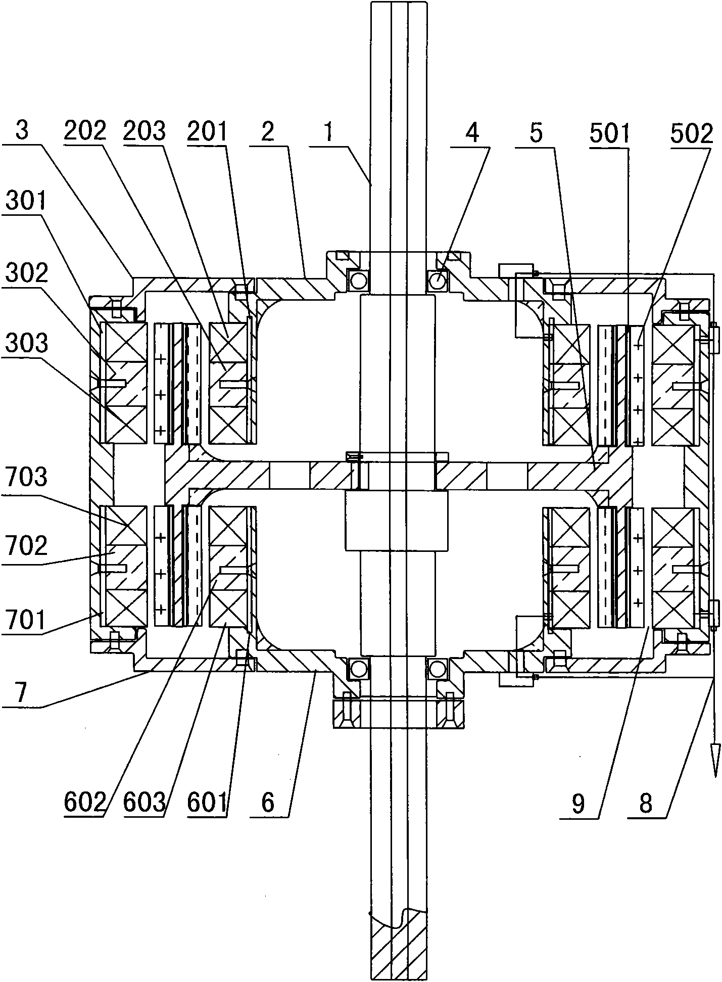
[0020] Example: attached figure 1 , a structural cross-sectional schematic diagram of an ironless multi-stator permanent magnet high-efficiency generator.

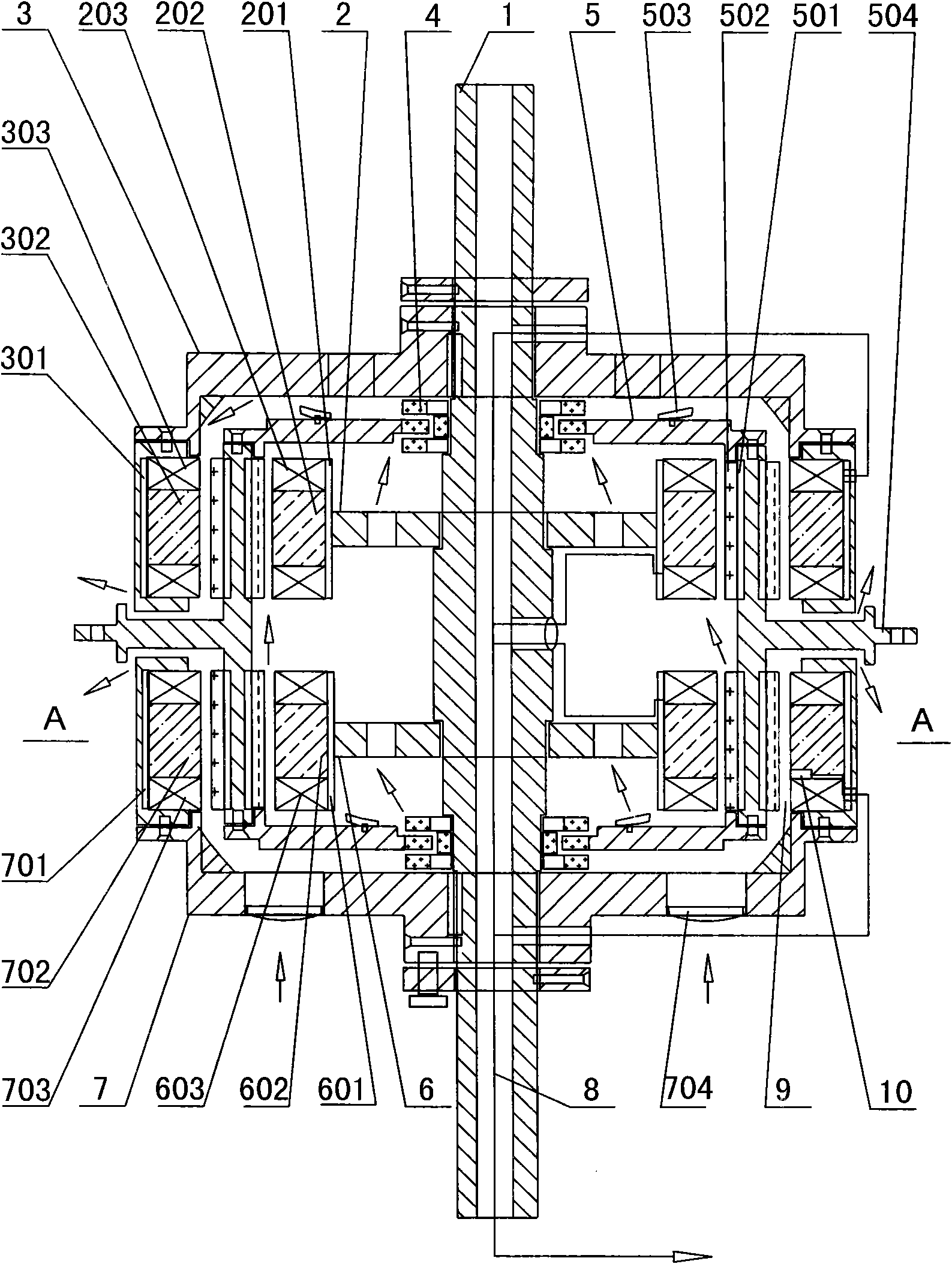
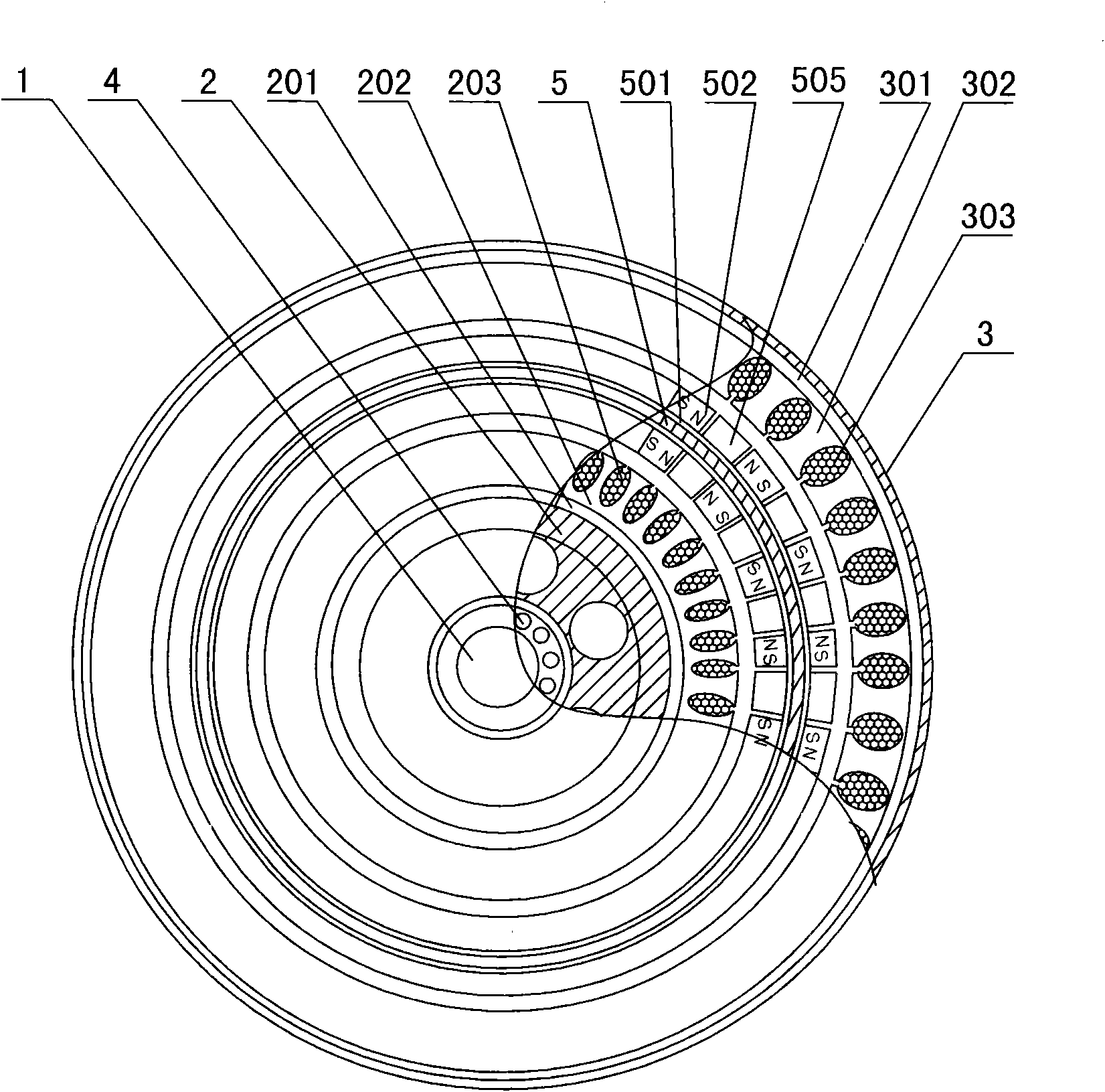
[0021] The first stator 2 and the second stator 6 are processed into a bowl-shaped shell shape, and are respectively arranged on the inside of the circumference of the rotor 5, and the main shaft 1 is supported by the bearing 4, and the wires 8 are respectively connected to the stator windings 203, 603, and pass through the inside of the shell. The pipeline leads to the junction box; the third stator 3 and the fourth stator 7 are processed into a cylindrical body, which is arranged outside the circumference of the rotor. The cylindrical body can be disassembled and processed and then fixed into one body with screws. Two sets of magnetic washers, frames, and windings are arranged along the circumferential direction, and the central round holes on both sides of the shell of the cylindrical body are respectively fixed with th...


PUM


Abstract

The invention discloses an efficient permanent magnet generator with no-iron core and multiple stator, belonging to the clean energy wind power generation equipment technology field. The efficient permanent magnet generator with no-iron core and multiple stator is characterized in that a first stator and a third stator, a second stator and a fourth stator are arranged at the inner side and the outer side of a rotor respectively; a center circular hole of a stator housing is fixedly connected with a main shaft; leads are connected with stator windings separately and are leaded out through a pipeline; the main shaft is supported by a bearing or a magnetic bearing in an end cover; the rotor is processed to an I-shaped disc or cylinder shape by metal, and the two ends of the rotor are armoredwith a magnetism conducting coil or a magnetism isolating coil and a permanent magnetic sheet along the inner circumference direction and outer circumference direction respectively; the center is fixed through the main shaft; or the rotor interface is extended from a symmetrical middle interspace formed by the first stator and the third stator to be as a transmission part of the outer rotor, wherein, air gaps are arranged between the rotor and the stators separately. The product with no iron core has the advantages of resource-saving, simple structure, few parts, small material consumption, light weight, small volume, high efficiency, low cost, simple production technology, and being suitable for an assembly line mass production.

Description

technical field [0001] The invention relates to an iron-core multi-stator permanent magnet high-efficiency generator, which belongs to the technical field of clean energy, and in particular to a high-efficiency power generation equipment suitable for wind power generation. Background technique [0002] According to the motor principle that the electromagnetic force is proportional to the magnetic flux and current, the low-speed direct-drive wind turbine must achieve a relatively large power, and to reduce the diameter of the motor, reduce the volume and weight, the electromagnetic force must be significantly increased; because The traditional generator or permanent magnet generator is composed of a stator and a rotor. When manufacturing a higher-power motor, the volume of the stator and the rotor must be increased in proportion. The defect of low efficiency obviously cannot meet the requirements of wind power generation. Contents of the invention [0003] The object of th...

Claims


Application Information

Patent Timeline
IPC IPC(8): H02K16/00H02K21/12H02K9/06
Inventor 陈国宝
Owner 中润国力集团有限公司
Learn More