Hybrid drive full-bridge synchronous rectifier

A synchronous rectifier and hybrid drive technology, applied in the direction of output power conversion device, AC power input conversion to DC power output, high-efficiency power electronic conversion, etc., can solve the problem of high circuit cost and achieve the effect of reducing the number

Inactive Publication Date: 2011-08-31
ZHEJIANG UNIV
View PDF2 Cites 29 Cited by
  • Summary
  • Abstract
  • Description
  • Claims
  • Application Information

AI Technical Summary

Problems solved by technology

However, in full-bridge applications, each synchronous tube needs a detection driver chip, a total of 4 is required, and the circuit cost is high

Method used


Image

  • Hybrid drive full-bridge synchronous rectifier
  • Hybrid drive full-bridge synchronous rectifier
  • Hybrid drive full-bridge synchronous rectifier

Examples


Embodiment Construction

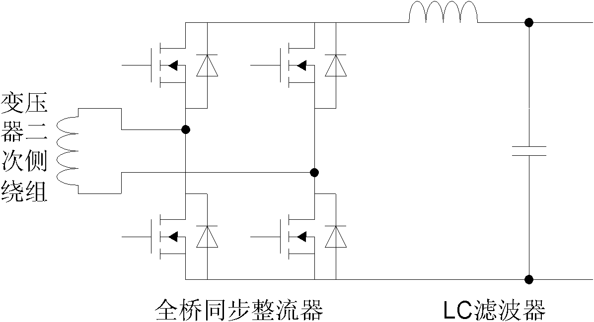
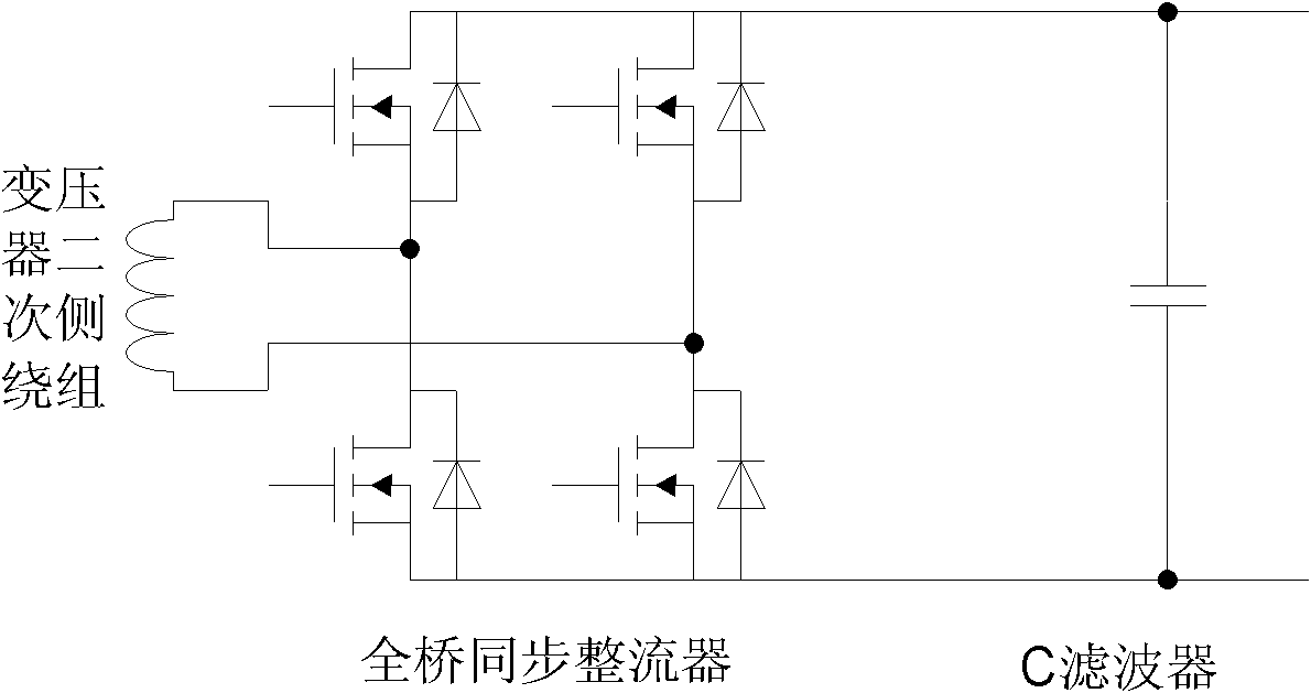
[0044] In the traditional output rectification structure, there are two types of voltage output type and current output type, such as figure 1 , 2 shown. Which type of output rectification structure to use depends on the topology of the circuit. For example, voltage-type output is suitable for traditional full-bridge PWM, phase-shifted full-bridge, half-bridge, push-pull and parallel resonance circuits, while current-type output is usually suitable for current-type push Pull, series resonance, LLC series resonance circuit, etc. Among these two types of rectifiers, synchronous rectification with a full-bridge structure requires 4 synchronous transistors and their corresponding drive circuits.

[0045] The voltage control type self-drive is applied to the voltage output type rectifier. As mentioned above, there is a situation where the current flows in the opposite direction, resulting in low light load efficiency. To solve this problem, a current detection circuit must be use...


PUM


Abstract

The invention relates to a synchronous rectification circuit, which aims at providing a hybrid drive full-bridge synchronous rectifier. The full-bridge synchronous rectifier comprises at least one voltage control type driving circuit and at least one current control type driving circuit, wherein the voltage control type driving circuit is used for driving two synchronous tubes of the full-bridge synchronous rectifier on the basis of a transformer auxiliary winding or an output winding waveform; and the current control type driving circuit is used for detecting a current of a transformer secondary winding or currents of the other two synchronous tubes of the full-bridge synchronous rectifier and driving the two synchronous tubes on the basis of detection signals. In a structure of the current type output rectifier, a hybrid drive mode is adopted; therefore, the defect that the current type output rectifier cannot be driven in a voltage control manner in the prior art can be overcome by using the voltage control type driving circuit; meanwhile, the number of current detecting elements can be largely reduced.

Description

technical field [0001] The invention relates to the field of electric energy conversion, in particular to a synchronous rectification circuit, which is a driving mode of a synchronous rectification tube in a novel full-bridge synchronous rectification circuit which adopts a combination of a voltage type drive and a current type drive at the same time. Background technique [0002] At present, in the development process of power electronics, the application of low voltage and high current output has become a very important development direction. In this case, the loss of the rectifier on the secondary side of the converter accounts for most of the overall loss, especially for a circuit using diode rectification, the ratio of the loss caused by the conduction voltage drop to the output power is VF / Vo, where VF is the forward conduction voltage drop of the rectifier device, and Vo is the output voltage. Even the best Schottky diodes today have a forward voltage drop of 0.3V. W...

Claims


Application Information

Patent Timeline
Patent Type & Authority Applications(China)
IPC IPC(8): H02M7/219
CPCY02B70/1408Y02B70/10
Inventor 张军明张国兴汪剑峰
Owner ZHEJIANG UNIV
Why Eureka
Try Eureka