Frequency doubler

A frequency multiplier and transistor technology, applied in power oscillators, electrical components, etc., can solve problems such as difficult and expensive oscillator design

Active Publication Date: 2013-04-10
IND TECH RES INST
View PDF0 Cites 0 Cited by
  • Summary
  • Abstract
  • Description
  • Claims
  • Application Information

AI Technical Summary

Problems solved by technology

Oscillator design that takes into account both high frequency and wide frequency is quite expensive and difficult

Method used


Image

  • Frequency doubler
  • Frequency doubler
  • Frequency doubler

Examples


Embodiment Construction

[0035] The following content includes various embodiments of the present invention, and the content is not intended to limit the scope of the present invention. The actual scope of the present invention should still be based on the description of the scope of the patent application.

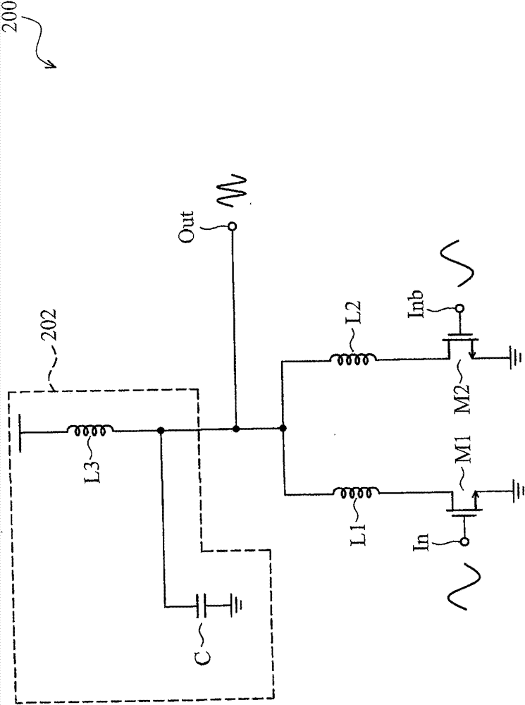
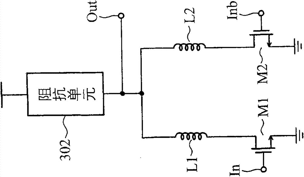
[0036] figure 2 One embodiment of the frequency multiplier of the present invention is illustrated. The frequency multiplier 200 includes two input terminals and an output terminal, and the two input terminals can be used to receive a positive-phase oscillation signal In and an anti-phase oscillation signal Inb provided by an oscillator (not shown in the figure). The positive-phase and negative-phase oscillating signals In and Inb have a phase difference of 180 degrees from each other. The frequency multiplier 200 generates a higher frequency oscillating signal Out at the output terminal under the operation of the above-mentioned positive-phase and anti-phase oscillating signals In and Inb.

...


PUM


Abstract

The invention discloses a frequency doubler which is used for processing a normal phase oscillator signal and an opposite phase oscillator signal for generating a signal of higher frequency on an output end. The frequency doubler comprises a first transistor, a second transistor, a first inductor and a second inductor, wherein the first end of the first transistor and the first end of the second transistor are on the same potential; the normal phase oscillator signal and the opposite phase oscillator signal are respectively input into the frequency doubler by the control end of the first transistor and the control end of the second transistor; the first inductor and the second inductor respectively couple the second end of the first transistor and the second end of the second transistor to the output end of the frequency doubler; and the first inductor and the second inductor can be realized by respectively independent inductance components and also can be realized by a symmetrical inductor with mutual inductance effect.

Description

technical field [0001] The present invention relates to a frequency doubler. Background technique [0002] Wireless communication technology is increasingly developed, and the frequency range used has reached Giga Hertz (Giga Hertz). figure 1 List several current common wireless communication applications, among which, labels 102 to 116 are respectively Terrestrial Trunk Radio Communication System (TETRA), Global System for Mobile Communications 900 (GSM900), GSM 1800, third generation mobile communication technology (3G), Wireless local area network 802.11b / g (WLAN 802.11b / g), WLAN 802.11a, ultra wideband (UWB), and wireless high-definition communication (wireless HD). It can be found that the current frequency of wireless communication even reaches 60 GHz. [0003] With such a high communication frequency, the receiver and transmitter of the wireless signal must be implemented with a relatively high-level process technology, which is expensive. In addition, in addition ...

Claims


Application Information

Patent Timeline
Patent Type & Authority Patents(China)
IPC IPC(8): H03B19/06
Inventor 张智翔林荣茂杨清渊
Owner IND TECH RES INST
Why Eureka
Try Eureka