
Integrated optic chip for three-axis fiber optic gyroscope

A fiber optic gyroscope and integrated optics technology, applied in the field of integrated optics and fiber optic sensors, can solve the problems of high process cost, large insertion loss, and complicated process, and achieve the effects of simple preparation process, low loss, and high electro-optic coefficient

Inactive Publication Date: 2011-09-07
SOUTHEAST UNIV
View PDF1 Cites 9 Cited by
  • Summary
  • Abstract
  • Description
  • Claims
  • Application Information

AI Technical Summary

Problems solved by technology

The cost of this modulator is high, the process is complicated, and the insertion loss of the optical fiber is also relatively large.

Method used


Image

  • Integrated optic chip for three-axis fiber optic gyroscope
  • Integrated optic chip for three-axis fiber optic gyroscope
  • Integrated optic chip for three-axis fiber optic gyroscope

Examples


Embodiment Construction

[0018] The technical solution of the present invention will be further described below in conjunction with the accompanying drawings.

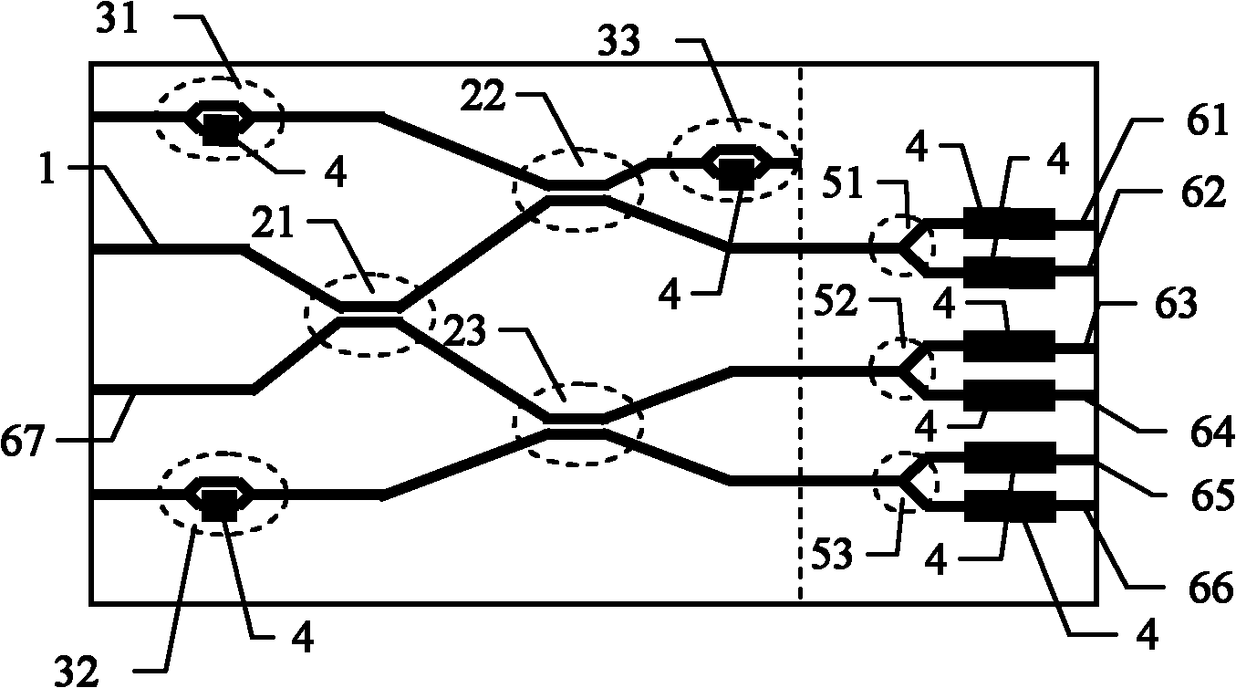
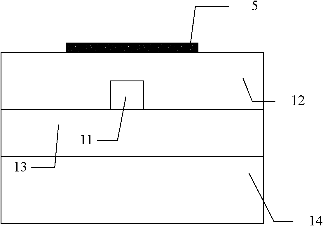
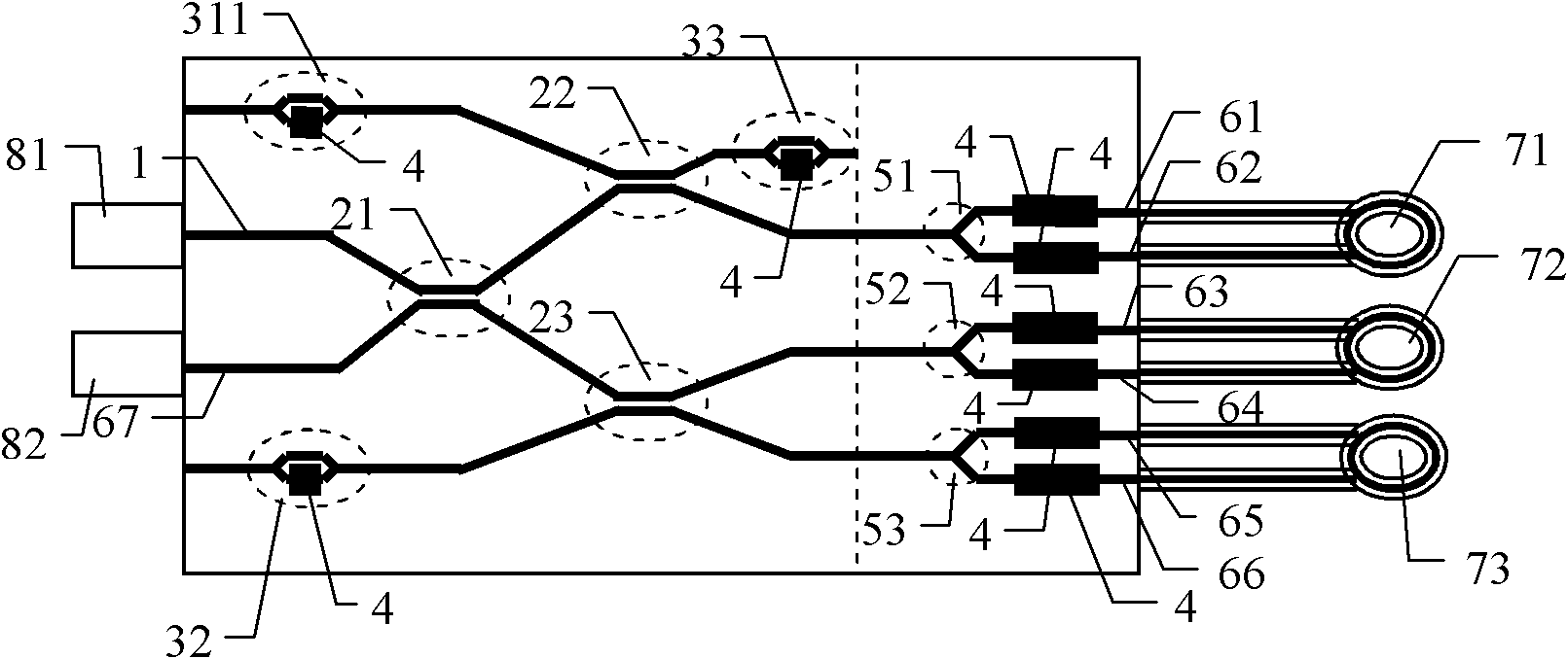
[0019] The integrated optical chip structure of the three-axis fiber optic gyroscope proposed by the present invention is as follows: figure 1 As shown: the chip includes an input optical waveguide 1, a first directional coupler 21, a second directional coupler 22, a third directional coupler 23, a Mach-Zehnder optical waveguide attenuator, a metal electrode 4, a first Y Branch coupler 51, second Y branch coupler 52, third Y branch coupler 53, output optical waveguide. From input to output, respectively set

[0020] The input optical waveguide 1, the seventh output optical waveguide 67, the optical waveguide attenuator 3 and the metal electrode 4 of two Mach-Zehnder structures, the first directional coupler 21, the second directional coupler 22 and the third directional coupler 23, the optical waveguide attenuator 31 of the first Mach-Zehnde...


PUM


Abstract

The invention provides an integrated optic chip for a three-axis fiber optic gyroscope, in which an input optical waveguide, a first direction coupler, a second direction coupler, a third direction coupler, an optical waveguide attenuator with a Mach-Zehnder structure, an output optical waveguide, a first Y-branch coupler, a second Y-branch coupler, a third Y-branch coupler and a designed metal electrode are integrated. The chip is prepared by low-loss organic polymer optical waveguide material and organic polymer electrooptical material. In comparison with a conventional discrete device optical system, a plurality of waveguide devices with key functions are uniformly integrated on the chip; the multifunctional chip can implement functions, such as modulation, attenuation, splitting, wave combination and the like, on light beams; and the multifunctional chip has the advantages of excellent consistency, high stability, low power, small volume, light weight and the like, and can be used for developing the three-axis fiber optic gyroscope.

Description

technical field [0001] The invention belongs to the technical field of integrated optics and optical fiber sensors, in particular to an integrated optical chip for a three-axis optical fiber gyroscope. Background technique [0002] Fiber optic gyroscope is an inertial angular velocity measuring instrument, which is mainly used in platform navigation, missile guidance, aiming stability, attitude control, positioning and other fields. The principle of the fiber optic gyroscope to detect angular velocity is the Sagnac effect: that is, after the light beam enters the system, it is divided into two beams of light waves that propagate in opposite directions. After passing through the same optical path, they propagate in opposite directions and return to the splitting point in phase. If there is a rotational angular velocity relative to the inertial space around the axis perpendicular to the plane where the optical path is located, the optical path of the light beam propagating in ...

Claims


Application Information

Patent Timeline
Patent Type & Authority Applications(China)
IPC IPC(8): G01C19/72
Inventor 张彤薛晓军雷威张晓阳李威
Owner SOUTHEAST UNIV
Learn More