Multi-pulse gate delay range gating laser imaging radar

A laser imaging radar, gate delay technology, applied in the direction of re-radiation of electromagnetic waves, utilization of re-radiation, measurement devices, etc., can solve problems such as low range resolution

Inactive Publication Date: 2011-09-07
HARBIN INST OF TECH
View PDF5 Cites 27 Cited by
  • Summary
  • Abstract
  • Description
  • Claims
  • Application Information

AI Technical Summary

Problems solved by technology

[0003] The purpose of the present invention is to solve the problem of low range resolution of the existing range-gated laser imaging radar, and to provide a multi-pulse gate delay range-gated laser imaging radar

Method used


Image

  • Multi-pulse gate delay range gating laser imaging radar
  • Multi-pulse gate delay range gating laser imaging radar
  • Multi-pulse gate delay range gating laser imaging radar

Examples


specific Embodiment approach 1

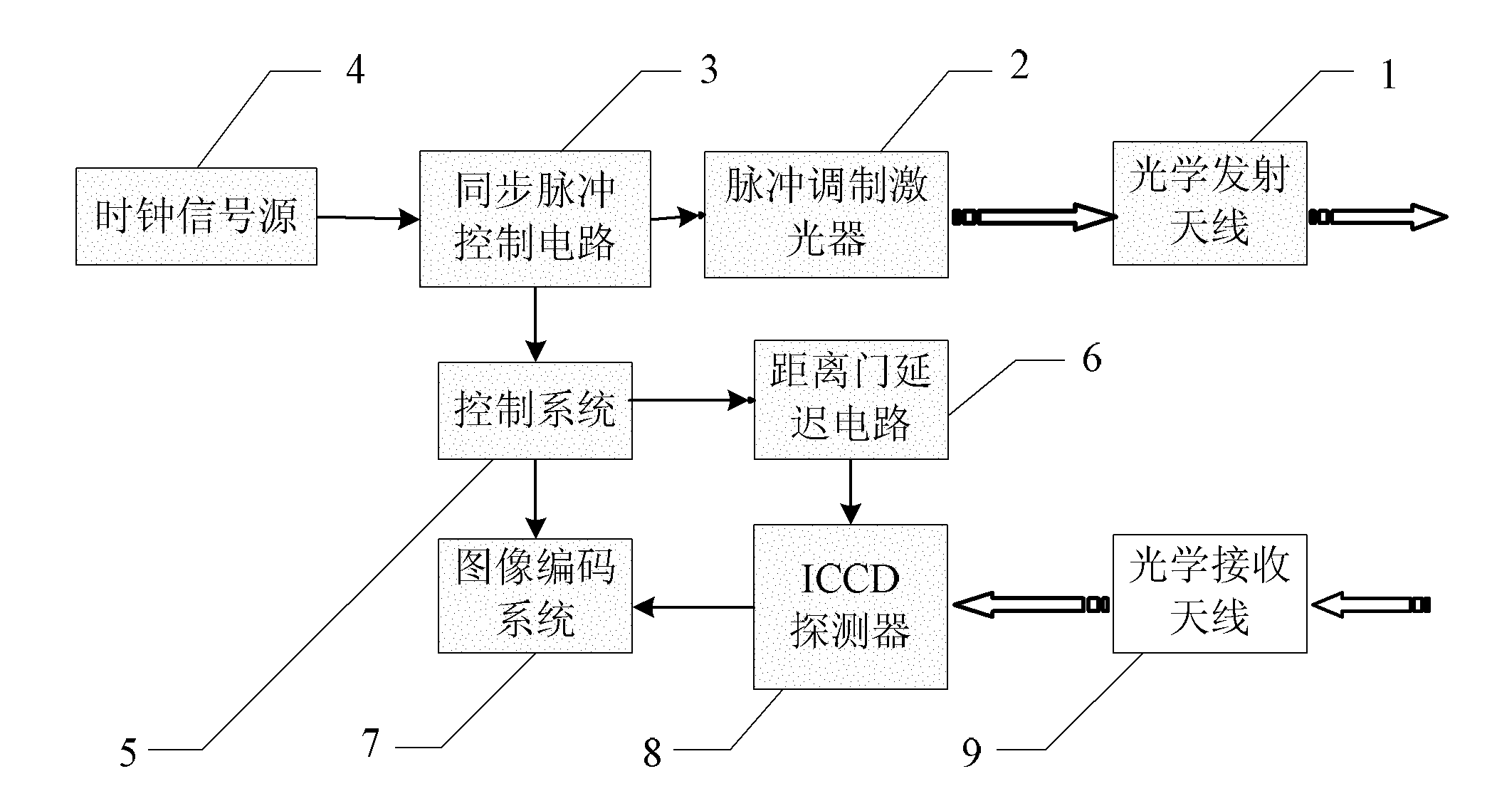
[0019] Specific implementation mode one: the following combination figure 1 Describe this embodiment, this embodiment consists of an optical transmitting antenna 1, a pulse modulation laser 2, a synchronous pulse control circuit 3, a clock signal source 4, a control system 5, a range gate delay circuit 6, an image coding system 7, an ICCD detector 8 and The optical receiving antenna is composed of 9,

[0020] The clock signal output end of the clock signal source 4 is connected to the clock signal input end of the synchronous pulse control circuit 3, and the drive pulse signal output end of the synchronous pulse control circuit 3 is connected to the drive pulse signal input end of the pulse modulation laser 2, and the laser of the pulse modulation laser 2 The pulse signal output end is connected to the optical input end of the optical transmitting antenna 1;

[0021] The control signal output end of the synchronous pulse control circuit 3 is connected to the control signal in...

specific Embodiment approach 2

[0026] Embodiment 2: This embodiment is a further description of Embodiment 1. Corresponding to each laser pulse signal emitted by the pulse-modulated laser 2 , the ICCD detector 8 performs a 2D target intensity image sampling. Others are the same as the first embodiment.

specific Embodiment approach 3

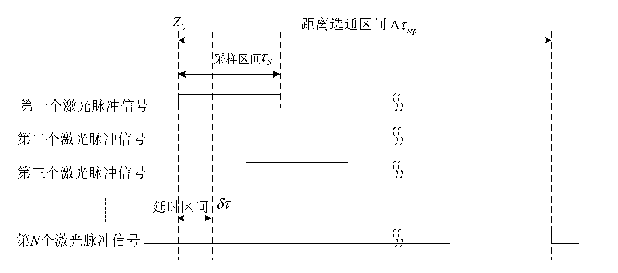
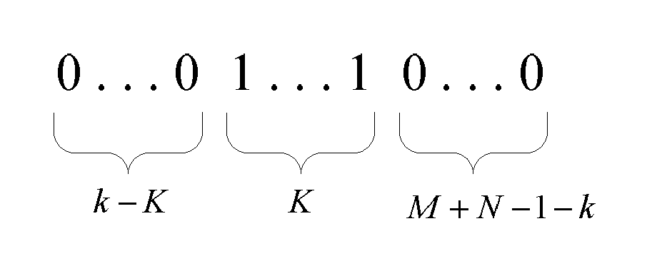
[0027] Specific implementation mode three: the following combination figure 2 and image 3 Describe this embodiment mode, this embodiment mode is the further explanation to embodiment mode 2, described pulse modulation laser 2 is used for carrying out N detection to target, each detection is realized by a laser pulse signal that pulse modulation laser 2 emits; ICCD detection The device 8 is used for each range gating interval Δτ set in the range gate stp Sampling the laser echo pulse signal of the target to complete a detection; in two adjacent detections, the range gate start time corresponding to the latter detection is relative to the range gate start time corresponding to the previous detection Delay a delay interval δτ, set the sampling interval to τ S , then τ S =Mδτ, where M is a positive integer, then Δτ stp =(M+N-1)δτ. Others are the same as the second embodiment.

[0028] In this embodiment, the pulse-modulated laser 2 can be a semiconductor laser with a centr...


PUM


Abstract

The invention provides a multi-pulse gate delay range gating laser imaging radar and belongs to the technical field of laser radars, wherein the radar provided by the invention solving the problem of the existing range gating laser imaging radar, such as low range resolution. The multi-pulse gate delay range gating laser imaging radar is characterized in that the clock signal of a clock signal source is output to a synchronous pulse control circuit; the synchronous pulse control circuit transmits a drive pulse signal to a pulse modulation laser, and transmits a delay signal to a control system at the same time; the control system can transmit the ordinal number of drive pulse signals emitted by the synchronous pulse control circuit to an image coding system after the control system transmits the delay signal to a range gate delay circuit; the image coding system numbers the received optical signal images according to the same ordinal number; the optical signal images are collected by an ICCD (intensified charge coupled device) detector; and an optical transmitting antenna and an optical receiving antenna are respectively used for transmitting laser beams and receiving a target laser echo pulse signal. The multi-pulse gate delay range gating laser imaging radar is applicable to the range detection of a target.

Description

technical field [0001] The invention relates to a multi-pulse gate delay distance gating laser imaging radar, which belongs to the technical field of laser radar. Background technique [0002] Range-gated lidar imaging radar adopts laser active illumination method, uses range gating technology, detects the echo signals of targets at different distances in sequence according to time, and obtains 3D imaging information of the target. The range resolution of range-gated lidar imaging depends first on the range-gate interval, and secondly on the influence of range gate and laser pulse signal fluctuations. Narrow pulse width and short sampling interval can enable the radar to achieve higher range resolution. Generally, to improve the range resolution of range-gated lidar imaging, it is necessary to shorten the laser pulse width and sampling interval, and increase the peak power of laser emission, which will impose strict requirements on the laser and the receiving system, and the...

Claims


Application Information

Patent Timeline
Patent Type & Authority Applications(China)
IPC IPC(8): G01S17/89G01S7/481
Inventor 吴龙赵远张宇刘丽萍张勇靳晨飞吴杰孙秀东
Owner HARBIN INST OF TECH
Why Eureka
Try Eureka