Manufacturing method and product of intra-head femur stent

A technology of support frame and femoral head, applied in the direction of femoral head, hip joint, joint implant, etc., can solve the problem of non-uniformity of porous structure, and achieve the effect of uniform internal structure

Inactive Publication Date: 2011-09-14
北京畅想天行医疗技术有限公司
View PDF5 Cites 10 Cited by
  • Summary
  • Abstract
  • Description
  • Claims
  • Application Information

AI Technical Summary

Problems solved by technology

Most of the mechanical processing methods currently in use are difficult to make the frame body of the scaffold into a porous structure similar to the structure of bone tissue
Chinese patent ZL200810111686.6 discloses a method of us

Method used


Image

  • Manufacturing method and product of intra-head femur stent
  • Manufacturing method and product of intra-head femur stent
  • Manufacturing method and product of intra-head femur stent

Examples


Embodiment Construction

[0013] The present invention will be further described below in conjunction with the accompanying drawings and embodiments.

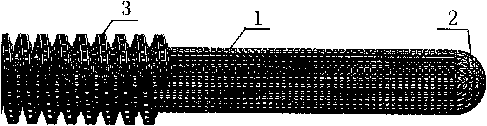
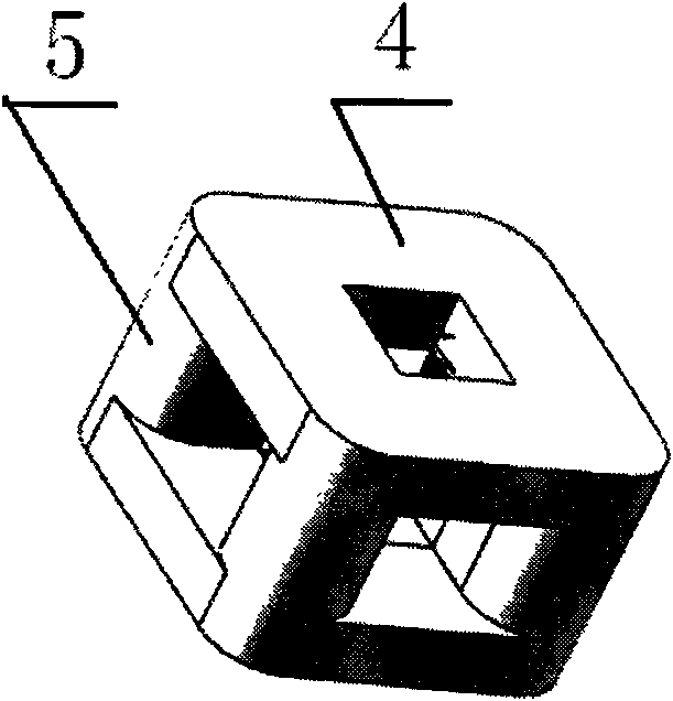
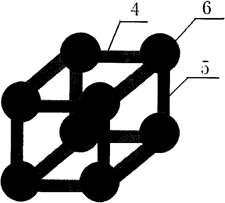
[0014] like figure 1 As shown, the general structure of the femoral head internal support frame of the present invention is the same as the applicant's previous patent application "201010573866.3 A kind of femoral head internal support frame", which is composed of three parts: head 2, body 1, and tail 3 Cylindrical body, the front end head 2 is hemispherical, the body 1 is cylindrical, and the tail 3 is a cylinder with external thread. Its microstructure is composed of superposition of small units with the same structure, and each small unit is as follows figure 2 or image 3 The six-sided frame body shown.

[0015] figure 2 Shown is an embodiment of the microscopic structure of the scaffold in the femoral head of the present invention. The picture shows a small structural unit, which is a hollow rectangular hexahedral frame body composed of 12 e...


PUM

PropertyMeasurementUnit
Pore sizeaaaaaaaaaa

Abstract

The invention discloses a method for manufacturing an intra-head femur stent. The method manufactures the designed product by means of laser beam scanning controlled by a computer to sinter and superpose metal powder materials in layers. The essential microstructure of each part of the intra-head femur stent prepared by the method is formed of units of the same structure that are superposed, and each small unit is a rectangular hexagonal frame formed of 12 edges. The finished product of the stent has enough strength and meanwhile, is coarse in the surface of the body, provided with a regular porous structure inside the body and suitable for the growth of bone tissue.

Description

technical field [0001] The invention relates to a preparation method for preparing a femoral head inner support frame as a human body implant; the invention also relates to a femoral head inner support frame prepared according to the method. Background technique [0002] The common treatment for osteonecrosis of the femoral head is core decompression. In order to prevent accelerated femoral head collapse due to bone defect and femoral neck weakness caused by core decompression, braces are implanted inside the femoral head to provide support. This implant is called a femoral intracapsular scaffold. In order for the scaffold to be well combined with the bone tissue, the scaffold should have a rough outer surface and a porous frame structure. Most of the mechanical processing methods currently in use are difficult to make the frame body of the scaffold into a porous structure similar to the structure of bone tissue. Chinese patent ZL200810111686.6 discloses a method of using...

Claims


Application Information

Patent Timeline
IPC IPC(8): A61F2/36
Inventor 沈龙吴春生邱芹尹晓宇包娟娟
Owner 北京畅想天行医疗技术有限公司
Why Eureka
Try Eureka