Sliding compression continuous solid-liquid separator

A technology of a solid-liquid separator and a pressure regulating mechanism, which is applied in the direction of a press, filtration separation, separation method, etc., and can solve problems such as limited stroke of a hydraulic cylinder, difficulty in pressing, and unfavorable increase in output.

Inactive Publication Date: 2011-09-14
ZHEJIANG HUAZHANG TECH
View PDF7 Cites 6 Cited by
  • Summary
  • Abstract
  • Description
  • Claims
  • Application Information

AI Technical Summary

Problems solved by technology

[0004] 1. Due to the hydraulic reciprocating pressurization, only intermittent operation can be adopted, and the tape running, pressing and unloading must be carried out step by step, so the efficiency is low
In addition, because of the intermittent operation, it is difficult to uniform the cloth, which leads to different pressing effects.
[0005] 2. Since the pressing pressure is completely provided by the hydraulic cylinder, and the stroke of the hydraulic cylinder is limited, the number of filter plates of each equipment is difficult to compare with the traditional box-type filter press. For example, the ordinary plate-type filter press can achieve 100 plates. Above, and the utility model is generally about 10 boards, which is very unfavorable to increase production and reduce equipment cost
[0006] In terms of high dehydration pressure of continuous operation filter press equipment, if the publication dat...

Method used


Image

  • Sliding compression continuous solid-liquid separator
  • Sliding compression continuous solid-liquid separator
  • Sliding compression continuous solid-liquid separator

Examples


Embodiment 1

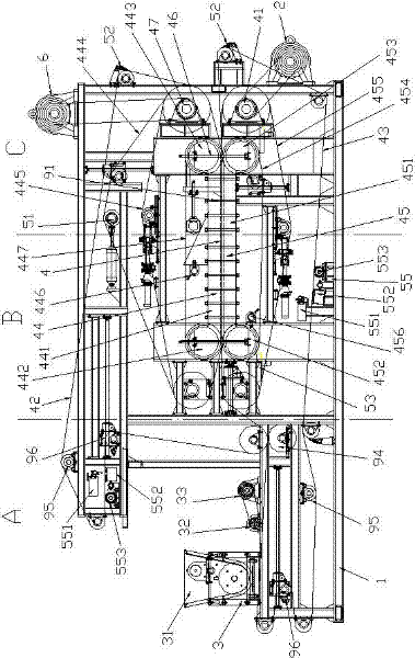
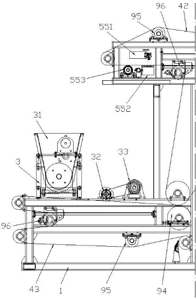
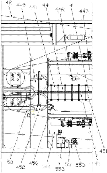
[0054] See Figure 1 to Figure 5 , Figure 25 to Figure 27 , The sliding pressurized continuous solid-liquid separator in this embodiment includes a frame 1, a driving device with a transmission belt, a feeding device 3, an upper filter belt 42, a lower filter belt 43, a pressing zone 4 and auxiliary devices, among which, The auxiliary device includes a tension roller 51, a scraper device 52, a water receiving device 53, a correction device and a filter belt cleaning device 55, and the filter belt cleaning device 55 further includes a flushing pipe 551, a vacuum box 552 and a rolling brush 553. The feeding device 3 includes a distributor 31, a screed roller 32, and a screed roller motor 33; the driving device with a transmission belt includes an upper driving device 6 with an upper transmission belt 445 and a lower driving device 2 with a lower transmission belt 455, and An upper driving roller 47 is provided in the upper driving device 6, and a lower driving roller 41 is provid...

Embodiment 2

[0072] See Figure 5 to Figure 9 , Figure 25 to Figure 27 , The sliding pressurized continuous solid-liquid separator in this embodiment includes a frame 1, a driving device with a transmission belt, a feeding device 3, an upper filter belt 42, a lower filter belt 43, a pressing zone 4 and auxiliary devices, among which, The auxiliary device includes a tension roller 51, a scraper device 52, a water receiving device 53, a correction device and a filter belt cleaning device 55, and the filter belt cleaning device 55 further includes a flushing pipe 551, a vacuum box 552 and a rolling brush 553. The feeding device 3 includes a distributor 31, a screed roller 32, and a screed roller motor 33; the driving device with a transmission belt is a lower driving device 2 with a lower transmission belt 455, and the lower driving device 2 is provided with a lower driving roller 41 With the transmission motor, the lower filter belt 43 is wrapped around the lower driving roller 42, and the lo...

Embodiment 3

[0081] See Figure 10 to Figure 16 , Figure 25 to Figure 27 , The sliding pressurized continuous solid-liquid separator in this embodiment includes a frame 1, a driving device with a transmission belt, a feeding device 3, an upper filter belt 42, a lower filter belt 43, a pressing zone 4 and auxiliary devices, among which, The auxiliary device includes a tension roller 51, a scraper device 52, a water receiving device 53, a correction device and a filter belt cleaning device 55, and the filter belt cleaning device 55 further includes a flushing pipe 551, a vacuum box 552 and a rolling brush 553. The feeding device 3 includes a distributor 31, a screed roller 32, and a screed roller motor 33; the driving device with a transmission belt is a lower driving device 2 with a lower transmission belt 455, and the lower driving device 2 is provided with a lower driving roller 41 With the transmission motor, the lower filter belt 43 is wrapped around the lower driving roller 42, and the ...


PUM

PropertyMeasurementUnit
Hardnessaaaaaaaaaa
Hardnessaaaaaaaaaa

Abstract

The invention relates to a sliding compression continuous solid-liquid separator. Solid-liquid separation equipment capable of adapting to dehydrating adhesive and slippery materials and running continuously is absent at present. The sliding compression continuous solid-liquid separator comprises a frame, a feeding device, a lower filter belt, a squeezing area and a driving device, and is characterized in that: the squeezing area comprises an upper compression device and a lower compression device; the upper compression device comprises at least one upper compression unit comprising an upper compression block, an upper left compression roller, an upper right compression roller and an upper sliding rubber belt; the upper sliding rubber belt coats and winds the upper left compression roller, the upper compression block and the upper right compression roller; the lower compression device comprises a lower compression block, a lower left compression roller, a lower right compression roller and a lower sliding rubber belt; the lower sliding rubber belt coats and winds the lower left compression roller, the lower compression block and the lower right compression roller; the upper compression device is positioned over the lower compression device; a gap is formed between the upper compression device and the lower compression device; and the height of the gap is gradually reduced froman inlet to an outlet. The sliding compression continuous solid-liquid separator is reasonable in structural design and high in solid-liquid separation efficiency, and can adapt to dehydrating the adhesive and slippery materials and continuously operates.

Description

Technical field [0001] The invention relates to a solid-liquid separator, in particular to a sliding pressurized continuous solid-liquid separator, belonging to a high-pressure strong solid-liquid separation device, which is mainly suitable for sewage treatment plants, paper mills, food processing plants, chemical factories and Dehydration of micro-particle liquid-containing materials in farms. Background technique [0002] Water treatment plants, paper mills, food processing plants, chemical plants and breeding farms all produce a large amount of materials that need to be dehydrated. These materials are dehydrated, concentrated and then landfilled, which can save a lot of land and reduce sewage penetration. At the same time, many organic materials in these materials can be directly used for comprehensive utilization when they are concentrated to a certain solid content, thereby saving drying Dry energy, for example, when the solid content of paper-making deinking sludge is pres...

Claims


Application Information

Patent Timeline
IPC IPC(8): B01D33/04B01D33/64B30B9/24
Inventor 唐志超崔健袁帅李小整
Owner ZHEJIANG HUAZHANG TECH
Why Eureka
Try Eureka