
Forming die and forming method for nano-diaphragm special for filter press

A diaphragm and forming mold technology, which is applied in the field of filter press diaphragm forming mold manufacturing, can solve the problems that the nano-diaphragm filter cannot be formed, achieve good anti-fouling properties, eliminate static electricity, and not easy to absorb.

Inactive Publication Date: 2011-09-14
HANGZHOU XINGYUAN FILTER TECH
View PDF9 Cites 0 Cited by
  • Summary
  • Abstract
  • Description
  • Claims
  • Application Information

AI Technical Summary

Problems solved by technology

However, it cannot be used for forming nano-membrane filters

Method used


Image

  • Forming die and forming method for nano-diaphragm special for filter press
  • Forming die and forming method for nano-diaphragm special for filter press
  • Forming die and forming method for nano-diaphragm special for filter press

Examples


Embodiment 1

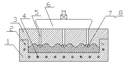
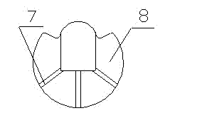
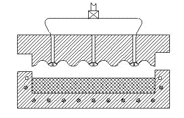
[0011] Embodiment 1: with reference to attached Figure 1-3 . A special nano-diaphragm forming mold for filter presses, which includes an upper mold 3 and a lower mold 1. There are multiple heating channels around the lower mold 1 and heating elements 4 are built in the heating channels. The molding surface of the upper mold 3 is A plurality of nozzles 7 are provided and the nozzles 7 communicate with the nano pressurizer 6 through the fluid channel 5 in the upper mold 3 body. The manufacture of the upper mold 3 and the lower mold 1 is a prior art, and will not be described here. Nano pressurization (jet) device 6 is prior art, does not describe at this.

[0012] The heating element 4 is an electric heating tube or an electric heating wire, and the installation of the electric heating tube or the electric heating wire and the heating channel in the lower mold 1 and the design of the electric heating tube or the electric heating wire terminal connected to the power control end...

Embodiment 2

[0015] Embodiment 2: On the basis of embodiment 1, the molding method of the special nano-diaphragm sheet molding mold for filter press, first the diaphragm light sheet after molding is placed in the lower film after heating, when the diaphragm light sheet positioned in the lower mold cavity When the sheet has just passed the critical point of melting, start the nano pressurizer 6, and the multiple nozzles 7 on the forming die surface of the upper mold 3 above the lower mold spray the nanomaterials onto the surface of the diaphragm light sheet, and then pressurize and close The upper mold forces the nano-layer sprayed on the diaphragm to blend into the surface of the diaphragm, and the nano-diaphragm is obtained after cooling. The pressure ejected from the nozzle 7 is greater than or equal to the pressure exerted by the upper die on the diaphragm. The nano material is nano ceramic powder, nano metal material. The nanolayer is larger than 0.1 microns.


PUM


Abstract

The invention relates to a forming die and a forming method for a nano-diaphragm special for a filter press which can bond a nano-material on an extruding surface of a diaphragm, and the forming die comprises an upper die and a lower die, wherein the lower die is provided with a plurality of heating channels at peripheral parts, and heating elements are disposed in the heating channels; the upper die is provided with a plurality of nozzles on the forming die surface, and the nozzles are communicated with a nano-presser through a liquid channel in the upper die body. The advantages are that: firstly, not only the preparation of a nano-diaphragm is realized, but also the nano-material can be fused on the diaphragm effectively; secondly, the prepared nano-diaphragm has ultra-strong anti-pollution capacity, and has a surface which is not only smooth and fine, not easy to absorb dust or oil stain, but also easy to clean; and not only the pressed filter cake can automatically fall off from the nano-diaphragm, but also the nano-surface has excellent anti-pollution performance; thirdly, the prepared nano-diaphragm has ultra-strong wear resistant, and the hardness of the diaphragm is significantly increased; fourthly, the prepared nano-diaphragm has an ultra-strong antistatic property, can effectively eliminate static phenomenon, and does not absorb dust particles.

Description

technical field [0001] The invention relates to a special nano-diaphragm molding die for a filter press capable of combining nanomaterials on the extrusion surface of a diaphragm and a molding method, belonging to the field of manufacturing diaphragm molding dies for a filter press. Background technique [0002] At present, the special diaphragm forming mold for filter press adopts hot runner mold for injection molding. During the hot runner mold molding process, the temperature of the plastic melt is accurately controlled in the runner system. The plastic can flow into each cavity in a more uniform state, resulting in parts with consistent quality, and the parts formed by the hot runner have good gate quality, low residual stress after demolding, and small deformation of the parts. However, it cannot be used for forming nano-diaphragm filters. Contents of the invention [0003] Design purpose: To avoid the deficiencies in the background technology, to design a special na...

Claims


Application Information

Patent Timeline
Patent Type & Authority Applications(China)
IPC IPC(8): B29C45/26B29C45/73B29C45/22
Inventor 周立武徐孝雅
Owner HANGZHOU XINGYUAN FILTER TECH
Learn More