
Dielectric substance discharge food storage device

A storage device and dielectric technology, applied in the direction of transportation and packaging, anti-rot containers, containers, etc., to reduce power consumption, achieve long-term storage, and reduce pollution

Inactive Publication Date: 2011-09-14
富科海科技(苏州)有限公司
View PDF2 Cites 1 Cited by
  • Summary
  • Abstract
  • Description
  • Claims
  • Application Information

AI Technical Summary

Problems solved by technology

However, as a food storage device designed using the principle of electronic sterilization, there have been no reports in this regard

Method used


Image

  • Dielectric substance discharge food storage device
  • Dielectric substance discharge food storage device
  • Dielectric substance discharge food storage device

Examples


Embodiment 1

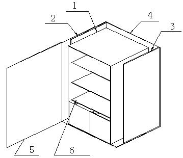
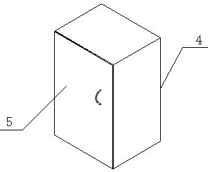
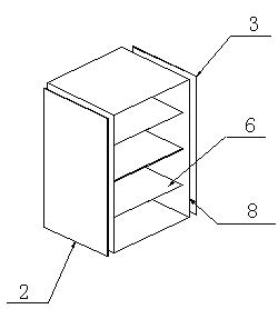
[0023] Examples of the present invention figure 1 shown. The dielectric discharge food storage device of the present invention is composed of a box shell 4, a food storage platform 6, a dielectric container and a catalyst structure 1, a power supply, a positive electrode plate 2 and a negative electrode plate 3; the dielectric container and the catalyst The structure is a five-sided cuboid container. The two side plates near the electrodes are made of stainless steel, and the inner wall of the structure is coated with a metal catalyst made of metal or metal oxide, and the rest of the separators are low dielectric materials; The electrical container and the catalyst structure are located inside the box body, and the side of the container facing the door 5 of the box body is empty, so that food can be placed in the container. A positive electrode plate and a negative electrode plate with discharge needles are respectively arranged on both sides of the mass container and the cat...

Embodiment 2

[0027] Examples of the present invention figure 1 shown. The dielectric discharge food storage device of the present invention is composed of a box shell 4, a food storage platform 6, a dielectric container and a catalyst structure 1, a power supply, a positive electrode plate 2 and a negative electrode plate 3; the dielectric container and the catalyst The structure is a four-sided cuboid container that runs through the front and back. The two side plates near the electrodes are made of aluminum alloy, and the inner wall of the structure is coated with a metal catalyst made of metal or metal oxide. The rest of the separators are made of low dielectric materials. The dielectric container and the catalyst structure are located inside the box body, and the front and back of the container pass through towards the box body door 5, so that food can be placed in the container, and the inner cavity of the dielectric container and the catalyst structure is placed on the food storage p...


PUM


Abstract

The invention discloses a dielectric substance discharge food storage device. The device consists of a box body shell (4), a stored food holding table (6), a dielectric substance container and contact agent structure (1), a power supply, a positive electrode plate (2) and a negative electrode plate (3); the dielectric substance container and contact agent structure is a cubic container located inside a box body; the stored food holding table is placed in an inner hollow cavity of the dielectric substance container and contact agent structure; the positive electrode plate and the negative electrode plate which are provided with discharge needles are arranged on both outer sides of the dielectric substance container and contact agent structure respectively; the discharge needles on the positive electrode plate and the negative electrode plate which are separated by the dielectric substance container and contact agent structure are remotely opposite to each other eye for eye; and the discharge needles on the electrode plates are connected with the power supply through circuits arranged on the electrode plates. When the dielectric substance discharge food storage device is powered on, voltage of 20,000 to 60,000 volts is exerted between the positive electrode plate and the negative electrode plate; by discharging through the discharge needles, a strong electric field is formed in the dielectric substance container and contact agent structure, so germs in the food storage device can be killed. The dielectric substance discharge food storage device can be used for food storage of families, supermarkets and shops.

Description

technical field [0001] The invention relates to a dielectric substance discharge food storage device, which belongs to the technical field of food storage equipment. Background technique [0002] For food storage, the commonly used method is low-temperature storage, and the equipment used is generally a refrigerator. Refrigerators rely on refrigeration to inhibit bacterial reproduction to achieve the purpose of storing food. Traditional compressor refrigeration consumes a lot of energy, and some refrigerants are more polluting to the environment. The food storage device kills the bacteria parasitic on the food in a very short time without destroying the nutritional structure of the food, stores the food at the desired temperature, and at the same time decomposes a small amount of TVOCs on the food to improve the health of the human body . [0003] There have been successful reports abroad on the use of high-voltage pulsed electric field, microwave, ray and other electronic...

Claims


Application Information

Patent Timeline
Patent Type & Authority Applications(China)
IPC IPC(8): B65D81/24
Inventor 洪昆喨
Owner 富科海科技(苏州)有限公司
Learn More