Polyethylene terephthalate (PET) esterification reaction kettle

A technology for an esterification reaction kettle and a kettle body, which is applied in the field of polyethylene terephthalate esterification reaction kettles, can solve the problems of hidden dangers of production accidents, high manufacturing costs, high operating costs and the like, and achieves reduction of production and operating costs. , The effect of reducing equipment maintenance work and capital investment

Active Publication Date: 2011-09-14
重庆万凯新材料科技有限公司
View PDF7 Cites 4 Cited by
  • Summary
  • Abstract
  • Description
  • Claims
  • Application Information

AI Technical Summary

Problems solved by technology

[0003] First of all, there is the input of agitator. The market price of a set of agitator (including motor, gearbox, mechanical seal, cooling system, lubricating oil, agitator, etc.) for the esterification reaction kettle with an annual output of 200,000 tons of PET is about 1 million. The investment cost of the enterprise is relatively high; although there are a small number of esterification reactors without agitator at present, the separation space between the heater and the esterification takes up a lot, and the equipment manufacturing cost is very high; secondly, the known esterification reactor with agitator In the production process of the reactor, there is a long-term continuous consumption of electric energy, and regular wear and tear of lubricating oil, mechanical seals, bearings, etc., resulting in high operating costs; thirdly, the esterification reactor agitator has abnormal mechanical wear during use Hidden dangers of production accidents due to other reasons; finally, due to the complex structure, there are a lot of equipment and process maintenance work

Method used


Image

  • Polyethylene terephthalate (PET) esterification reaction kettle
  • Polyethylene terephthalate (PET) esterification reaction kettle

Examples


Embodiment Construction

[0019] The present invention will be further described in detail below in conjunction with the accompanying drawings and embodiments.

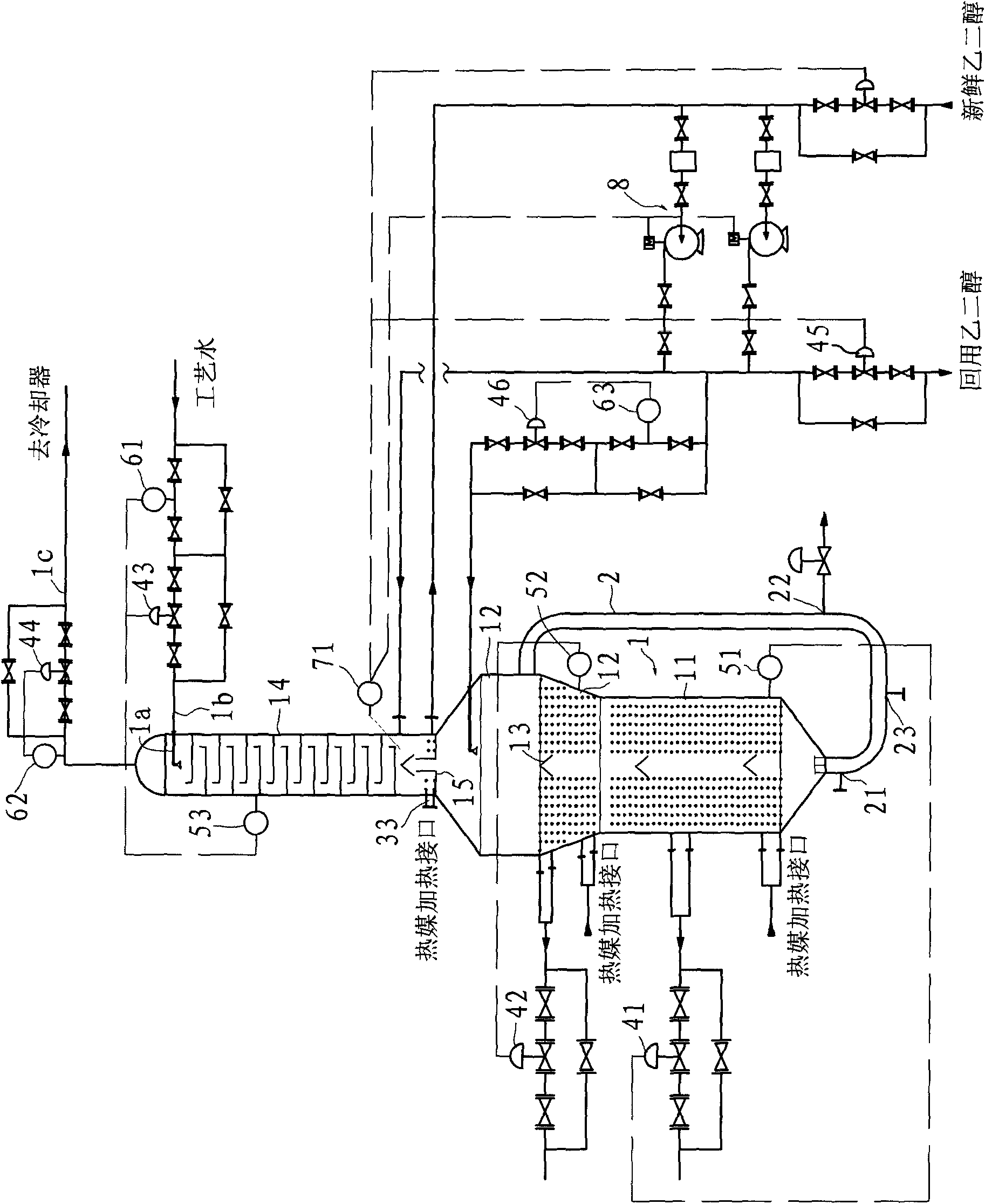
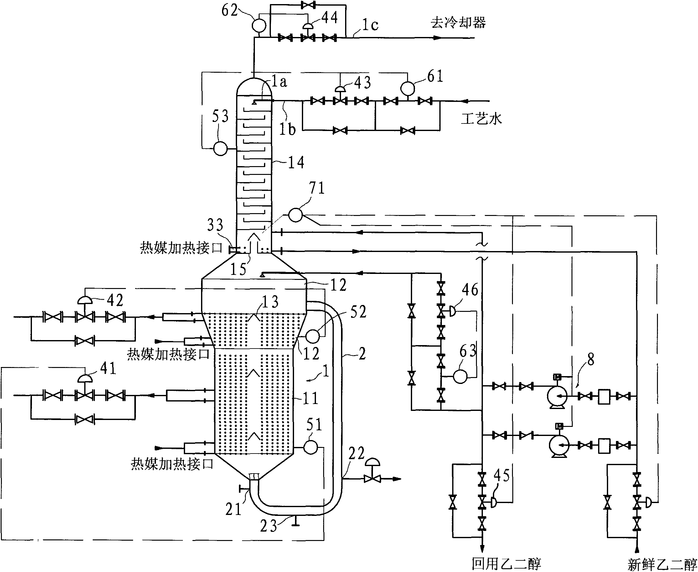
[0020] Such as figure 1 As shown, the PET esterification reaction kettle in this embodiment includes a kettle body 1, a process tower 14 and a circulation pipeline 2, and the kettle body 1 includes a small cavity 11 at the lower end and a large cavity 12 at the upper end, and the small cavity The inner diameter of 11 is smaller than the inner diameter of large cavity 12, and the axial length of small cavity 11 is greater than the axial length of large cavity 12. Both small cavity 11 and large cavity 12 are provided with turbulence that increases the flow resistance of the slurry. The flow plate 13 and the spoiler 13 are conical and arranged longitudinally. Corresponding to the lower ends of the small cavity 11 and the large cavity 12 are respectively provided a lower heating coil 31 and an upper heating coil 32 .

[0021] The circulation pip...


PUM


Abstract

The invention discloses a polyethylene terephthalate (PET) esterification reaction kettle, which comprises a kettle body. The PET esterification reaction kettle is characterized in that: the kettle body comprises a small cavity at the lower end and a big cavity at the upper end; a lower heating coil and an upper heating coil are arranged corresponding to the lower ends of the small cavity and the big cavity respectively; and the outer side of the kettle body is provided with a circulating pipeline, the feeding port of the circulating pipeline at the upper part is communicated with the big cavity, the discharge port of the circulating pipeline at the lower part is communicated with the small cavity, and the circulating pipeline is also provided with a slurry injection port and an esterification discharge hole spaced with the slurry injection port. Compared with the prior art, a stirrer is replaced by adopting the external circulating pipeline, so the purposes of saving energy and reducing consumption are fulfilled; and fund investment of stirrer equipment and supporting facilities of the traditional esterification reaction kettle is reduced, the production and operation costs are reduced, equipment maintenance operation in the production process is reduced, and production control is simplified.

Description

technical field [0001] The invention relates to an esterification reaction kettle, in particular to a polyethylene terephthalate (PET) esterification reaction kettle. Background technique [0002] At present, the design of the known esterification reactor of polyethylene terephthalate (PET) production plant is to set an "upper" or "lower" agitator on the reactor to promote the mixing of reactants. , flow rate, and speed up the material reaction. For such publications, you can refer to the Chinese utility model patent "New Efficient Esterification Reactor" (authorized announcement number CN2444948Y) with the patent number ZL00259656.3, and you can also refer to the Chinese utility model patent ZL200720002654.3. The new "Multi-Stage Stirring and Spraying Esterification Reactor" (authorized announcement number CN201002005Y), similar can also refer to CN201695019U, although this type of esterification reactor disclosed is more uniform in reactants, but there are many shortcoming...

Claims


Application Information

Patent Timeline
Patent Type & Authority Applications(China)
IPC IPC(8): C08G63/183C08G63/78
Inventor 朱树洲曾光建袁春剑郭茂起朱丹妮
Owner 重庆万凯新材料科技有限公司
Why Eureka
Try Eureka