Exhaust gas recirculation (EGR) ratio measuring device

A technology for measuring devices and pipes, which can be used in measuring devices, transmittance measurement, color/spectral characteristic measurement, etc., and can solve problems such as adverse effects on measurement accuracy, longer piping length, and deterioration in responsiveness, so as to promote cost, reduce Pump capacity, the effect of improving measurement accuracy

Active Publication Date: 2011-09-14
HORIBA LTD
View PDF6 Cites 8 Cited by
  • Summary
  • Abstract
  • Description
  • Claims
  • Application Information

AI Technical Summary

Problems solved by technology

[0014] However, in the above configuration, a cooler for dehumidification and piping for the cooler must be installed, so not only the size of the device will be increased, but also the length of the piping from the sampling point to the analyzer will be increased. lead to deterioration of the responsiveness of the measurement
Therefore

Method used


Image

  • Exhaust gas recirculation (EGR) ratio measuring device
  • Exhaust gas recirculation (EGR) ratio measuring device
  • Exhaust gas recirculation (EGR) ratio measuring device

Examples


Embodiment Construction

[0035] One embodiment of the present invention will be described below with reference to the drawings.

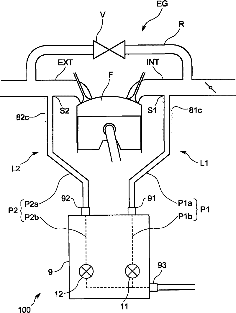
[0036] Such as figure 1 As shown, the EGR rate measurement device 100 of the present embodiment is based on the CO in the intake air introduced into the combustion chamber F of the internal combustion engine EG 2 Concentration and CO in the exhaust gas from the combustion chamber F 2 Concentration, measuring the EGR rate of the internal combustion engine EG.

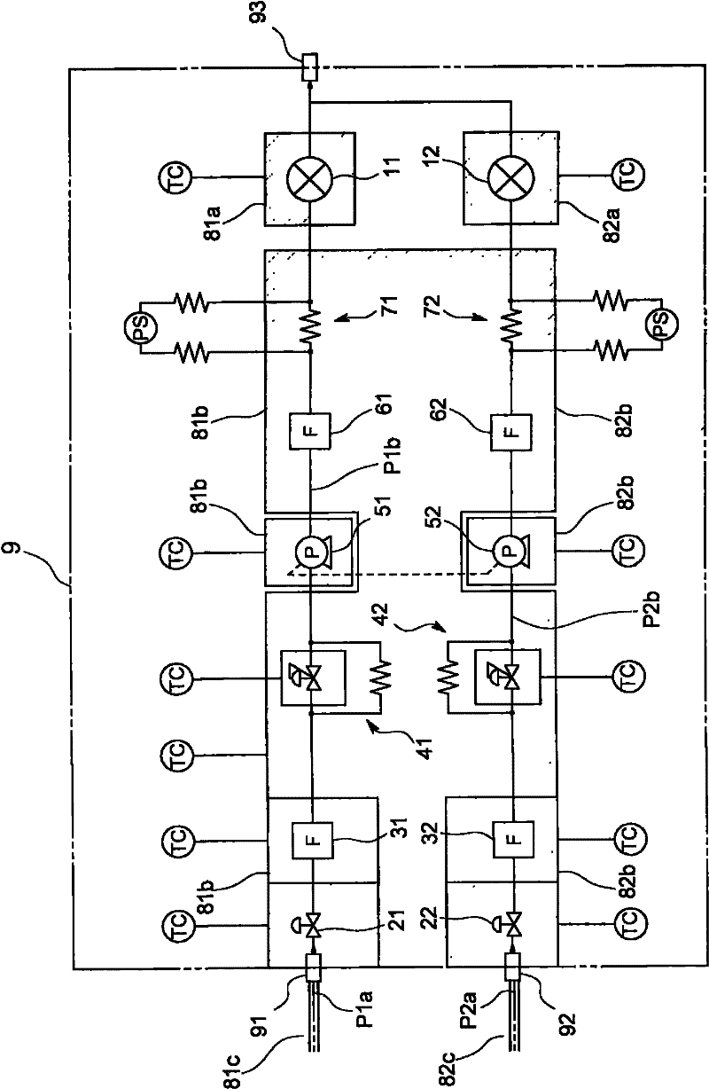
[0037] In more detail, the EGR rate measuring device 100 includes: measuring the CO in the intake air 2 Concentration of the first analyzer 11 and measure the CO in the exhaust 2 The second analyzer 12 of the concentration; the intake air introduction pipeline L1 is connected with the intake pipe INT of the internal combustion engine EG, and a part of the intake air is introduced into the first analyzer 11; the exhaust air introduction pipeline L2 is connected with the exhaust pipe of the internal combustion engin...


PUM


Abstract

In order to improve a measurement accuracy of an EGR ratio and to downsize the device and to save labor, the EGR ratio measuring device comprises a pair of nondispersive infrared gas analyzers, that have a function of correcting a water influence and that can measure a concentration of CO2 in a gas containing water, an intake air introduction line that is connected to an intake air pipe of an internal combustion engine and that introduces a part of the intake air into one nondispersive infrared gas analyzer without removing the water, an exhaust gas introduction line that is connected to an exhaust gas pipe of the internal combustion engine and that introduces a part of the exhaust gas into the other nondispersive infrared gas analyzer without removing the water, and a temperature adjusting mechanism; that keeps a temperature of whole of the introduction lines, and a temperature of the nondispersive infrared gas analyzers, so as not to condense dew, and a configuration of the intake air introduction line including a flow channel length is set to be substantially the same as a configuration of the exhaust introduction line including a flow channel length.

Description

technical field [0001] The invention relates to an EGR rate measuring device for measuring the EGR rate of an internal combustion engine with an exhaust gas recirculation system (EGR system), i.e. measuring the amount of gas recirculated from the exhaust pipe and also the amount of recirculation The ratio of intake air volume. Background technique [0002] Such as Figure 4 As shown, the EGR device is provided with a circulation path R connecting the exhaust pipe EXT of the internal combustion engine EG and the intake pipe INT, and the combustion temperature is reduced by recirculating the exhaust gas into intake air, thereby reducing NO x . In addition, as described in Patent Document 1, there is known a parameter called an EGR rate for controlling the return amount through the EGR valve V to optimize the combustion of the internal combustion engine EG. [0003] The EGR rate is the ratio of the gas recirculation amount from the exhaust pipe EXT to the intake air amount al...

Claims


Application Information

Patent Timeline
IPC IPC(8): F02M25/07G01N21/35G01N21/3504G01N21/61
CPCF02M25/0755G01N2021/158Y02T10/47G01N21/3504F02D41/0072F02D41/144F02M26/46Y02T10/40
Inventor 吉村友志宫井优
Owner HORIBA LTD
Why Eureka
Try Eureka