
Rotating plunger field energy converter

A rotary and converter technology, applied in the direction of fluid pressure actuation device, fluid pressure actuation system components, mechanical equipment, etc., can solve the problem of wasting energy and achieve the effect of simple structure

Inactive Publication Date: 2011-09-14
孙荣军
View PDF0 Cites 0 Cited by
  • Summary
  • Abstract
  • Description
  • Claims
  • Application Information

AI Technical Summary

Problems solved by technology

[0010] The technical problem to be solved by the present invention is to provide a plunger-type field energy converter, which solves the problem that the existing plunger cylinder uses the energy in the liquid for frictional work and wastes energy

Method used


Image

  • Rotating plunger field energy converter
  • Rotating plunger field energy converter
  • Rotating plunger field energy converter

Examples


Embodiment 1

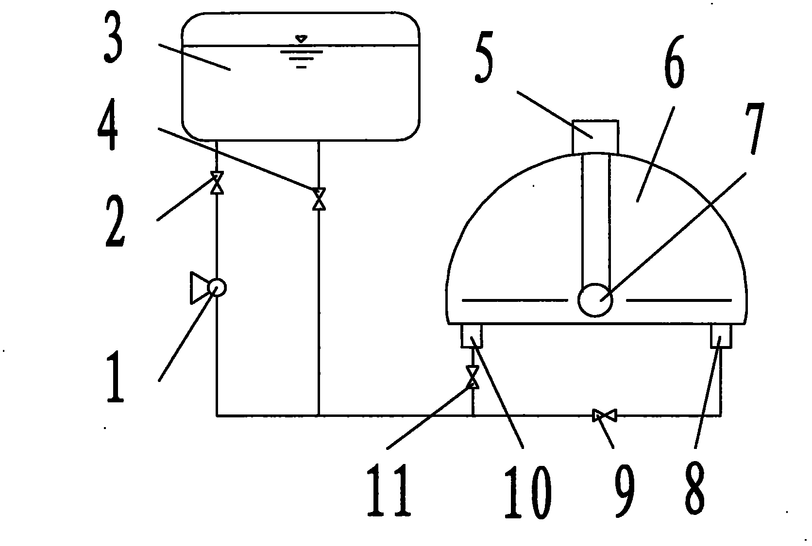
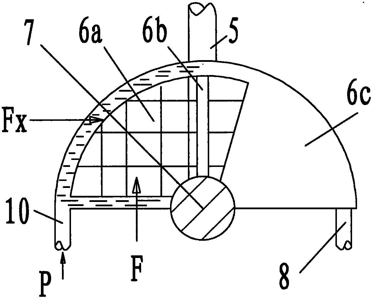
[0023] Embodiment 1: The equipment consists of a lifting pump 1, a lifting pump valve 2, a liquid storage tank 3, a liquid storage tank valve 4, an exhaust port 5, an internal energy generator 6, an output shaft 7, a first liquid inlet and outlet 8, a second The first inlet and outlet valve 9, the second inlet and outlet valve 10, and the second inlet and outlet valve 11, the outlet of the lift pump 1 is connected to the valve 2 of the lift pump, and the inlet is connected to the valve 4 of the liquid storage tank and the first inlet and outlet through pipelines The valve 9 and the liquid inlet and outlet valve 11 are connected, the valve 2 of the lift pump is connected with the liquid storage tank 3 through a pipeline, the lower part of the liquid storage tank 3 is connected with the valve 4 of the liquid storage tank, and the valve 4 of the liquid storage tank is connected with the lift pump 1 through a pipeline , the first liquid inlet and outlet valve 9, the second liquid i...

Embodiment 2

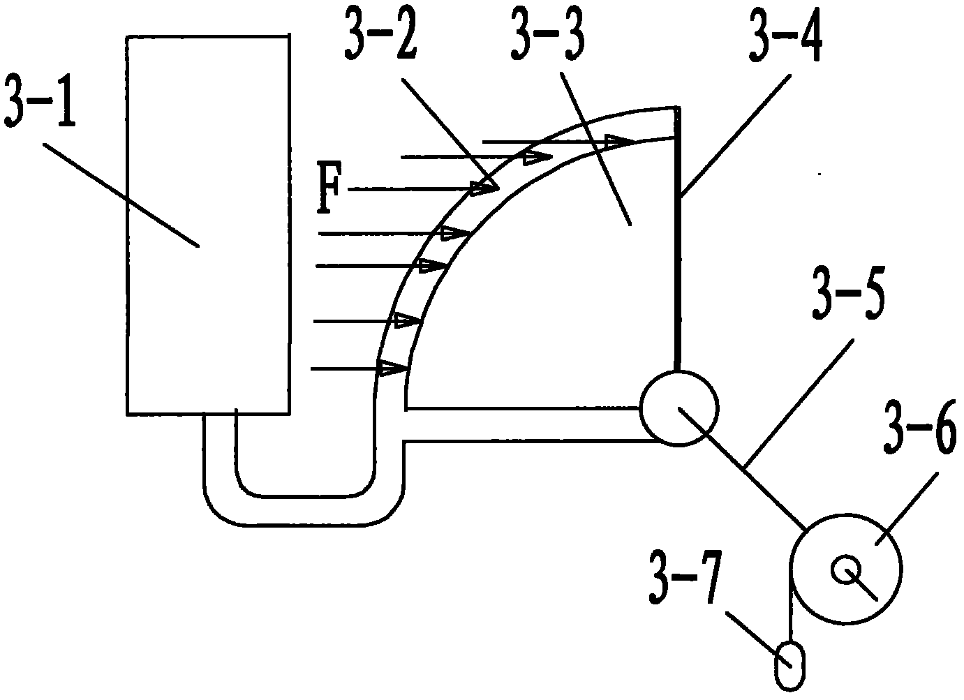
[0040] Embodiment 2: Experimental device and data analysis, including: liquid injector 3-1, housing 3-2, rotating floating body 3-3, seal 3-4, connecting shaft 3-5, torque disc 3-6 and weight 3-7.

[0041] Device composition:

[0042] 1. Shell: a 1\4 semicircle with a radius of 220mml and an inner hole width of 22mm, where the hole is located in the vertical direction. Material: ABS;

[0043] 2. Rotating floating body: a partial cylinder with a radius of 200mm and a thickness of 20.5mm and an angle of 100°. The diameter of the center shaft is 16mm, and the material is A3 steel.

[0044] 3. Sealing: The shaft seal is made of silica gel pad and cured by silica gel. Both sides are silicone tubes with an inner diameter of 4mm and an outer diameter of 6mm. Mercury is injected into the inside and embedded in the groove of the box.

[0045] 4. Moment plate: a pulley with a diameter of 250mm.

[0046] 5. Heavy hammer: ground balance weight, various specifications.

[0047]

[...


PUM

PropertyMeasurementUnit
Division valueaaaaaaaaaa

Abstract

The invention relates to a rotating plunger field energy converter, which belongs to an energy converter and is characterized in that an outlet of a lift pump is communicated with a liquid storage tank through a valve; an inlet of the lift pump is connected with a liquid outlet of the liquid storage tank and a first liquid inlet / outlet and a second liquid inlet / outlet of an internal energy generator through a pipe control valve and a pipeline control valve; the top part of the internal energy generator is provided with an exhaust port; a floating body of the internal energy generator is connected with an output shaft; and the output shaft outputs a torque to drive mechanical equipment. The invention has the advantages that: the rotating plunger field energy converter has a simple structure, the energy is generated by a carrier under the action of gravity field almost like the fall of an apple, the different point is the potential energy of the floating body which is the unique energy carrier of the rotating plunger field energy converter does not change, the energy return stroke is omitted by utilizing the characteristics of the gravity field, and the practical requirement of continuously-acquired internal energy of liquid is met in an earth gravity system.

Description

technical field [0001] The invention relates to an energy converter, in particular to a plunger type field energy converter. technical background [0002] It is well known that objects lose weight when placed in water. It can be understood that the weight lost by the object is converted into the internal energy of water, and the object becomes the carrier of internal energy. The increase of internal energy of water shows that the volume of water is expanded, and the expansion of water volume means that in the limited gravitational field space, the ability to obtain gravitational field energy has increased. [0003] When the internal energy increased by water is expressed by force, it is buoyancy, that is, buoyancy is a force that can only be released upwards, so the internal energy of water has directionality, that is to say, internal energy can only be released in the vertical direction, such as objects Ascending from the water to the space, the volume of the water will g...

Claims


Application Information

Patent Timeline
IPC IPC(8): F15B21/00
Inventor 孙荣军
Owner 孙荣军
Learn More