
Testing device and method for simulating backflow of propping agent

A testing device and proppant technology, which is applied in the fields of mining fluid, earthwork drilling, geophysical measurement, etc., can solve the problems that cannot reflect the real situation of proppant backflow, do not consider the influence of proppant backflow, and cannot simulate proppant backflow Influence and other issues, to achieve the effect of practical test method, good adaptability and simple structure

Active Publication Date: 2012-09-12
SOUTHWEST PETROLEUM UNIV
View PDF0 Cites 0 Cited by
  • Summary
  • Abstract
  • Description
  • Claims
  • Application Information

AI Technical Summary

Problems solved by technology

[0004] (1) The influence of different sanding concentrations on proppant reflux cannot be simulated;
[0005] (2) The influence of formation closure pressure on proppant flowback is not considered;
[0006] (3) The channel for the proppant to flow back from the near-wellbore fracture to the wellbore is the perforation hole. Without simulating this process, the real situation of proppant backflow cannot be reflected;
[0007] (4) It is impossible to carry out repeated experiments for different formation rocks, and the adaptability of the experimental results is poor;
[0008] (5) The relationship between fracture width and proppant backflow cannot be studied;
[0009] (6) The impact of formation temperature on proppant return cannot be ignored, and the real situation of proppant return cannot be reflected without simulating formation temperature

Method used


Image

  • Testing device and method for simulating backflow of propping agent
  • Testing device and method for simulating backflow of propping agent
  • Testing device and method for simulating backflow of propping agent

Examples


Embodiment Construction

[0036] Further illustrate the present invention according to accompanying drawing below.

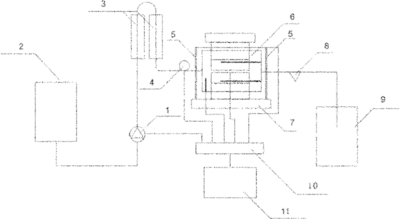
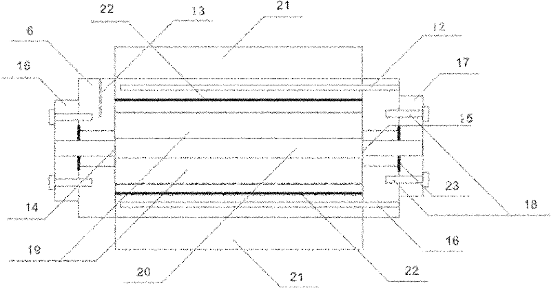
[0037] see figure 1 , figure 2 .

[0038] A test device for simulating proppant reflux, mainly composed of a liquid storage tank 2, a chamber pump 1, a pipeline heating jacket 3, a flow meter 4, a diversion chamber 6, a displacement sensor 5, a hydraulic press 7, a sand sample collector 8, a waste A liquid tank 9, a data acquisition control board 10, and a computer 11 are formed; the inside of the diversion chamber 6 has a deep hole for inserting an electric heating rod 12 and a temperature sensor 13; Between the plates 19 is a proppant laying area 20; the upper and lower parts of the diversion chamber 6 are connected with the hydraulic press 7 by a piston 21 and sealed by a sealing ring 22; the two ends of the diversion chamber 6 have a liquid inlet hole 14 and a liquid outlet hole respectively 15; the liquid inlet hole 14 is sequentially connected to the front joint 16, the flow me...


PUM


Abstract

The invention relates to a testing device and method for simulating the backflow of a propping agent. The testing device mainly comprises a liquid storage pot, a chamber pump, a pipeline heating sleeve, a flow meter, a diversion chamber, displacement sensors, an oil pressing machine, a sand sample collector, a waste liquid pot, a data acquiring and controlling panel, and a computer. The testing method comprises the following steps: propping agent is paved between two rock plates and is loaded in the diversion chamber, the chamber pump is opened to be driven by small discharge, the displacement sensors are arranged at two sides of the oil pressing machine, and are loaded to design pressure, the computer, the pipeline heating sleeve and an electric heating rod are started to adjust the discharge of the chamber pump, all data are transmitted to the computer through the data acquiring and controlling panel, the discharge is gradually increased to obtain the backflow critical flow velocityof the propping agent under certain closing pressure, and the closing pressure is gradually increased to obtain the backflow critical flow velocity of the propping agent under the condition of different closing pressure. The invention can simulate the real condition of the backflow of the propping agent in pressing cracks, and meets the testing requirement of the backflow of the propping agent under the condition of different environments.

Description

technical field [0001] The invention relates to a test device and method for simulating proppant backflow during oil and gas field development. Background technique [0002] Reservoir stimulation by proppant fracturing is the key engineering technology for oil and gas reservoir construction, production and efficient development. However, in the production process of fracturing construction wells, affected by factors such as formation fluid flow rate, proppant backflow often occurs. Proppant backflow will seriously affect the normal production of oil and gas wells. On the one hand, a fracture damage zone is formed in the formation near the wellbore, which seriously reduces the conductivity of propped fractures and causes a large drop in the production of oil and gas wells; Ground pipelines and instruments caused serious damage to production equipment and affected the smooth progress of production work. Therefore, it is of great significance to study the phenomenon of propp...

Claims


Application Information

Patent Timeline
Patent Type & Authority Patents(China)
IPC IPC(8): G01V9/00E21B43/267
Inventor 郭建春刘超王文耀
Owner SOUTHWEST PETROLEUM UNIV
Learn More