Charging method applying inverter circuit, application of inverter circuit and self-conversion charging inverter circuit

An inverter circuit, battery technology, applied in circuit devices, irreversible DC power input into AC power output, battery circuit devices, etc., can solve the problems of inability to charge the battery pack, battery overheating, explosion, etc. The effect of failure rate, ensuring continuous power supply, and reducing manufacturing costs

Inactive Publication Date: 2011-09-14
CHONGQING HWYTON ELECTRIC
View PDF0 Cites 2 Cited by
  • Summary
  • Abstract
  • Description
  • Claims
  • Application Information

AI Technical Summary

Problems solved by technology

Excessive charging voltage and excessive charging current can directly cause damage to the chemical substances in the battery, resulting in battery leakage
At the same time, it will cause the battery to overheat, lead to the deformation of the plate, and cause the battery to be damaged or even explode.
If the AC power drops to 60V after stepping down through the transformer, and then undergoes full-bridge rectification through the parasitic diodes on the four power transistors Q1, Q2, Q3, and Q4 in the full-bridge circuit, then the voltage is about 84V, which is too low to correct battery pack charging

Method used


Image

  • Charging method applying inverter circuit, application of inverter circuit and self-conversion charging inverter circuit
  • Charging method applying inverter circuit, application of inverter circuit and self-conversion charging inverter circuit
  • Charging method applying inverter circuit, application of inverter circuit and self-conversion charging inverter circuit

Examples


Embodiment Construction

[0021] Below in conjunction with accompanying drawing and embodiment the present invention will be further described:

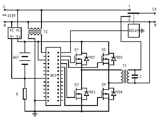
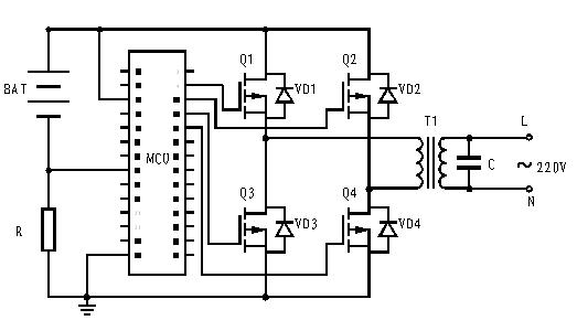
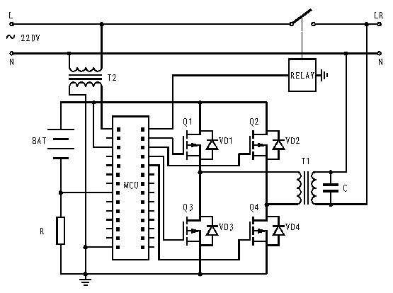
[0022] Such as figure 2 Shown, the method of the present invention is: it comprises inverter circuit, and described inverter circuit includes accumulator BAT, single-chip microcomputer MCU, public transformer T1 and by the first power tube Q1, the second power tube Q2, the A full-bridge circuit composed of three power transistors Q3 and fourth power transistor Q4, wherein each of the first power transistor Q1, second power transistor Q2, third power transistor Q3, and fourth power transistor Q4 contains parasitic diodes VD1 and VD2 respectively , VD3, VD4, use the inverter circuit to charge the storage battery, the specific method is:

[0023] Use the computer program to control the first power tube Q1, the second power tube Q2, the third power tube Q3, and the fourth power tube Q4 through the single-chip microcomputer MCU as follows: 1. The second power t...


PUM


Abstract

The invention relates to a charging method applying an inverter circuit, application of the inverter circuit and a self-conversion charging inverter circuit. The charging of a storage battery is realized by utilizing a full bridge inverter circuit and the method comprises the following steps of: controlling a drain electrode and a first power tube and a second power tube which are connected with the cathode of the storage battery to be in closed states by a singlechip; simultaneously and periodically controlling a third power tube and a fourth power tube to be switched on or off so as to obtain an appropriate voltage for charging the storage battery; and taking an output end of the inverter circuit as an input end of charging and connecting the output end of the inverter circuit with mains supply to realize continuous charging of the storage battery. In the invention, effective charging of the storage battery is realized by fully adopting the full bridge inverter circuit, the functions of the full bridge inverter circuit are expanded to make full use of the full bridge inverter circuit, the circuit cost is reduced, the operational reliability of the circuit is improved, and the mutual conversion between charging and inversion can be automatically realized, so that continuous power is supplied to a load.

Description

technical field [0001] The invention relates to an electric device, in particular to a circuit capable of charging a storage battery and performing inverter. Background technique [0002] The existing charging inverter circuit generally includes two parts: a charging circuit and a full-bridge inverter circuit, wherein the full-bridge inverter circuit includes a battery BAT, a single-chip microcomputer MCU, a transformer T1 and four power tubes Q1, A full-bridge circuit composed of Q2, Q3, and Q4, in which each power transistor contains parasitic diodes VD1, VD2, VD3, and VD4, such as figure 1 As shown, the input end of the charging circuit is connected to the mains, the output end of the charging circuit is connected to the positive and negative poles of the battery, the common contact of the contactor is connected to the power supply end of the live wire of the load, and the first normally open contact of the contactor is connected to the The live wire of the mains is conn...

Claims


Application Information

Patent Timeline
Patent Type & Authority Applications(China)
IPC IPC(8): H02J7/02H02M7/48
Inventor 冯波陈佑明
Owner CHONGQING HWYTON ELECTRIC
Why Eureka
Try Eureka