Continuously controllable transformer

A transformer and side column technology, applied in the field of continuously controllable transformers, can solve the problems of slow response speed and inability to continuously adjust the voltage, and achieve the effects of fast response speed, continuously adjustable voltage and large adjustment range

Inactive Publication Date: 2012-11-21
SHANDONG UNIV
View PDF0 Cites 0 Cited by
  • Summary
  • Abstract
  • Description
  • Claims
  • Application Information

AI Technical Summary

Problems solved by technology

This voltage regulation method cannot continuously adjust the voltage, and the response speed is slow.

Method used


Image

  • Continuously controllable transformer
  • Continuously controllable transformer
  • Continuously controllable transformer

Examples


Embodiment 1

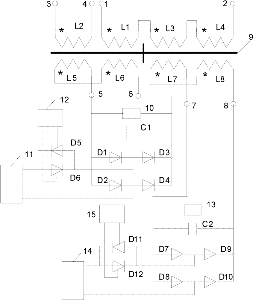
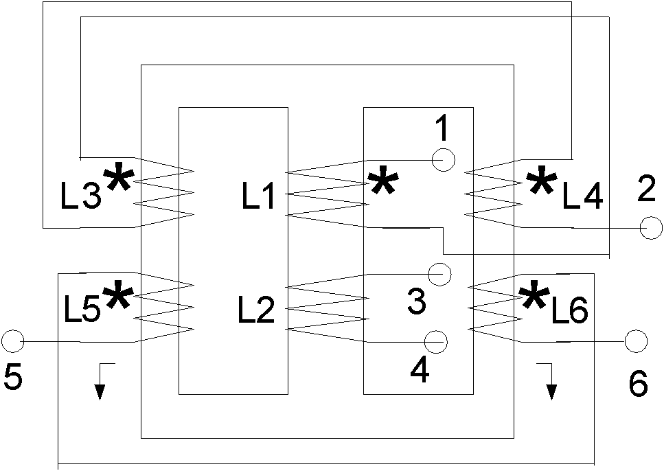
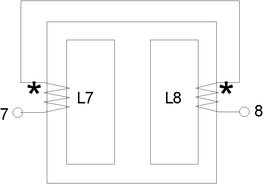
[0027] The topology and connection mode of a continuous controllable transformer are as follows: figure 1 shown. Figure 2a is the front view of the main core of the continuous controllable transformer; Figure 2b is a side view of the main core of the continuous controllable transformer; Figure 2c It is a top view of the main core of the continuous controllable transformer. The iron core of the continuous controllable transformer has 5 pillars, one center pillar and four side pillars. The five pillars are parallel to each other and arranged in a cross shape; the two ends of the five pillars have cross-shaped beams to form a magnetic flux circuit, and the side pillars I, The beams of the central column and side column II are on one straight line, the beams of side column III, central column, and side column IV are on another straight line, and the two straight lines are perpendicular to each other at the axis of the central column; side column I, side column II are respect...

Embodiment 2

[0048] In this embodiment, the number of turns of the AC coil L1 is equal to the number of turns of the AC coil L3.

[0049] When the current of the DC coil L5 and the DC coil L6 of the continuous controllable transformer is zero, and the current of the DC coil L7 and the DC coil L8 is also zero. The output voltage of the AC coil L2 is zero.

[0050] When the current of the DC coil L5 and the DC coil L6 of the continuous controllable transformer is zero, and the current of the DC coil L7 and the DC coil L8 increases from zero. The output voltage of the AC coil L2 increases from zero to half of the maximum output voltage.

[0051] When the current of the DC coil L5 and DC coil L6 of the continuous controllable transformer gradually decreases from the maximum to zero, and at the same time, the current of the DC coil L5 and the DC coil L6 gradually increases from zero to the maximum, the output voltage of the AC coil L2 is output from the maximum Half of the voltage ramps up to...


PUM


Abstract

The invention discloses a continuously controllable transformer. A continuously controllable transformer core comprises five pillars arranged in a cross shape, wherein the five pillars comprise a central pillar and four side pillars, are parallel to one another and form a magnetic flux loop by crossed beams; the central pillar is provided with AC coils L1 and L2; the side pillar I is provided with the AC coil L3 and a DC coil L5; the side pillar II is provided with the AC coil L4 and the DC coil L6; the side pillar III is provided with the DC coil L7; the side pillar IV is provided with the DC coil L8; the like end of the coil L5 is connected with that of the coil L6; the like end of the DC coil L7 is connected with that of the DC coil L8; an AC control power supply I is connected to the input end of a first full-bridge rectifier circuit by a pair of thyristors which are inversely connected in parallel; the AC control power supply II is connected to the input end of a second full-bridge rectifier circuit by another pair of thyristors which are inversely connected in parallel; and the output of the second full-bridge rectifier circuit is connected with terminals III and IV.

Description

technical field [0001] The invention relates to the technical field of power system power transmission and transformation and the field of industrial electrical appliances, in particular to a continuously controllable transformer. Background technique [0002] The transformation ratio of the power transformer is mostly fixed. Once the power transformer is manufactured, the number of turns of the primary coil and the number of turns of the secondary coil of the power transformer are determined, and the transformation ratio of the power transformer is determined. Power systems wish to have a means of adjusting voltage. The voltage can be adjusted by adjusting the reactive power, but the control equipment is complex, inconvenient to use, and the adjustment range is small. Electroplating enterprises, steel mills and industrial electrical fields require voltage and current regulation equipment with a large range and high power. [0003] It is most direct to adjust the power sys...

Claims


Application Information

Patent Timeline
Patent Type & Authority Patents(China)
IPC IPC(8): H02P13/00H01F27/24H01F27/30
Inventor 李晓明
Owner SHANDONG UNIV
Why Eureka
Try Eureka