Soybean milk machine

A soymilk machine and machine head technology, applied in the directions of milk substitutes, beverage preparation devices, household appliances, etc., can solve problems such as being difficult to clean, affecting the health, cleanliness, food hygiene and safety of drinkers, etc., and achieving easy processing and easy cleaning. Effect

Active Publication Date: 2014-07-16
ZHEJIANG SHAOXING SUPOR DOMESTIC ELECTRICAL APPLIANCE CO LTD
View PDF4 Cites 0 Cited by
  • Summary
  • Abstract
  • Description
  • Claims
  • Application Information

AI Technical Summary

Problems solved by technology

[0006] In addition, in the above-mentioned public documents, the grinding disc is fixed on the bottom of the bean-carrying cup and is not designed to be disassembled. It is difficult to clean the grinding disc, bean-carrying cup and feeding channel. After cleaning, food hygiene and safety, etc., it will cause problems and affect the health of drinkers.

Method used


Image

  • Soybean milk machine
  • Soybean milk machine
  • Soybean milk machine

Examples


Embodiment 1

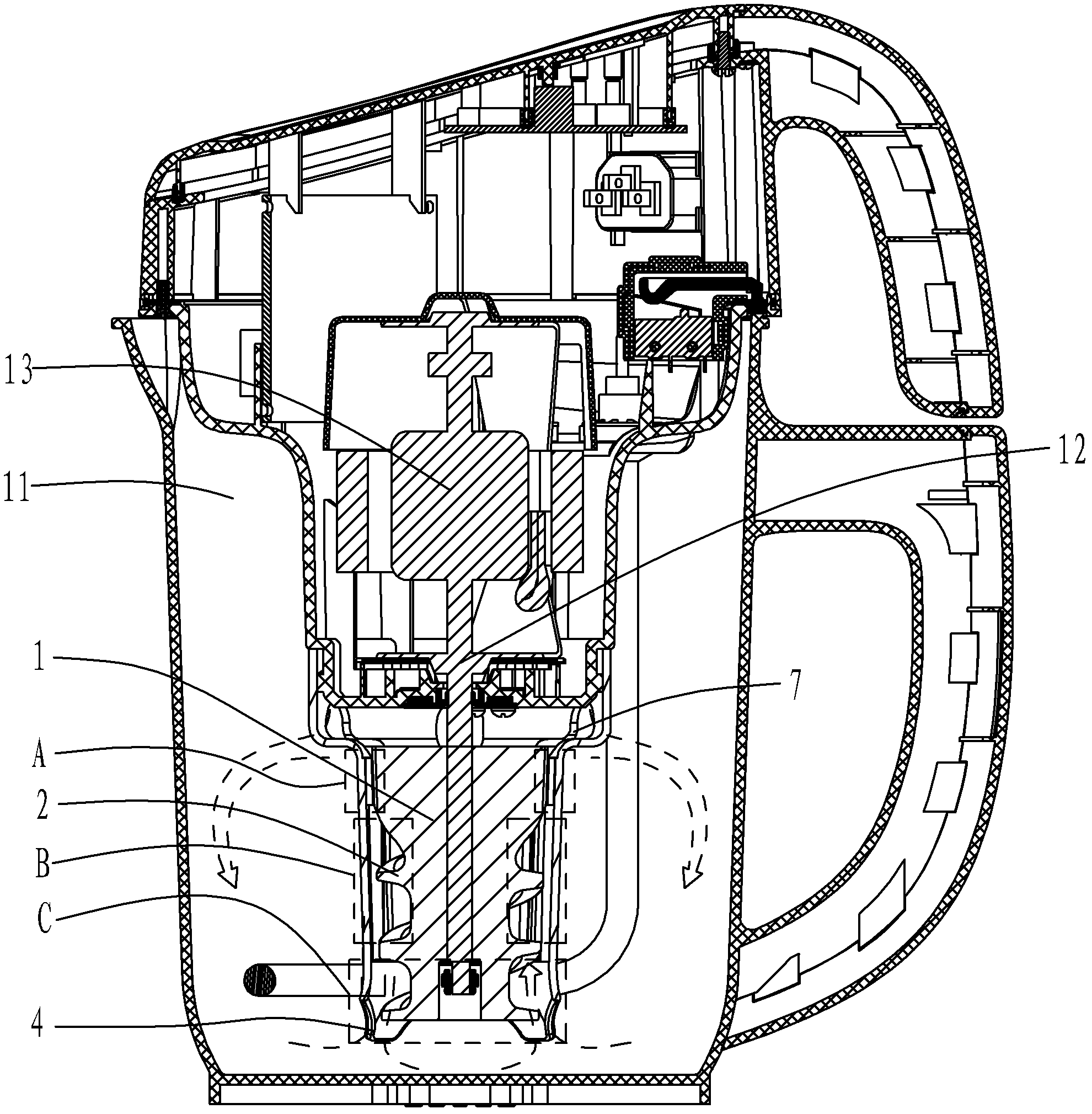
[0061] See attached Figure 1~12 , attached Figure 14~15 , attached Figure 18 , a soybean milk machine, comprising a cup body 11, a machine head buckled on the cup body 11, a motor 12 arranged in the machine head and an output shaft 13 connected with the motor 12, a liquid flow is provided at the lower part of the machine head The driving device 2 and the grinding device, the liquid flow driving device 2 is arranged below the grinding device.

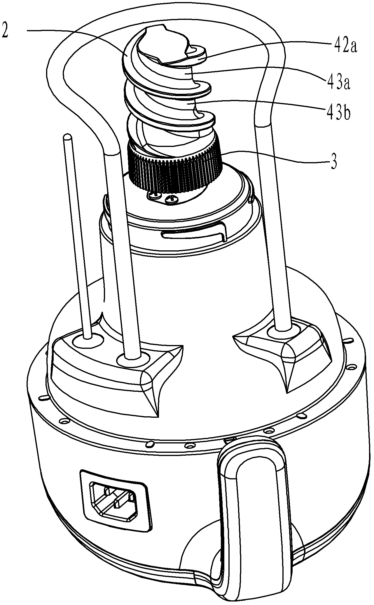
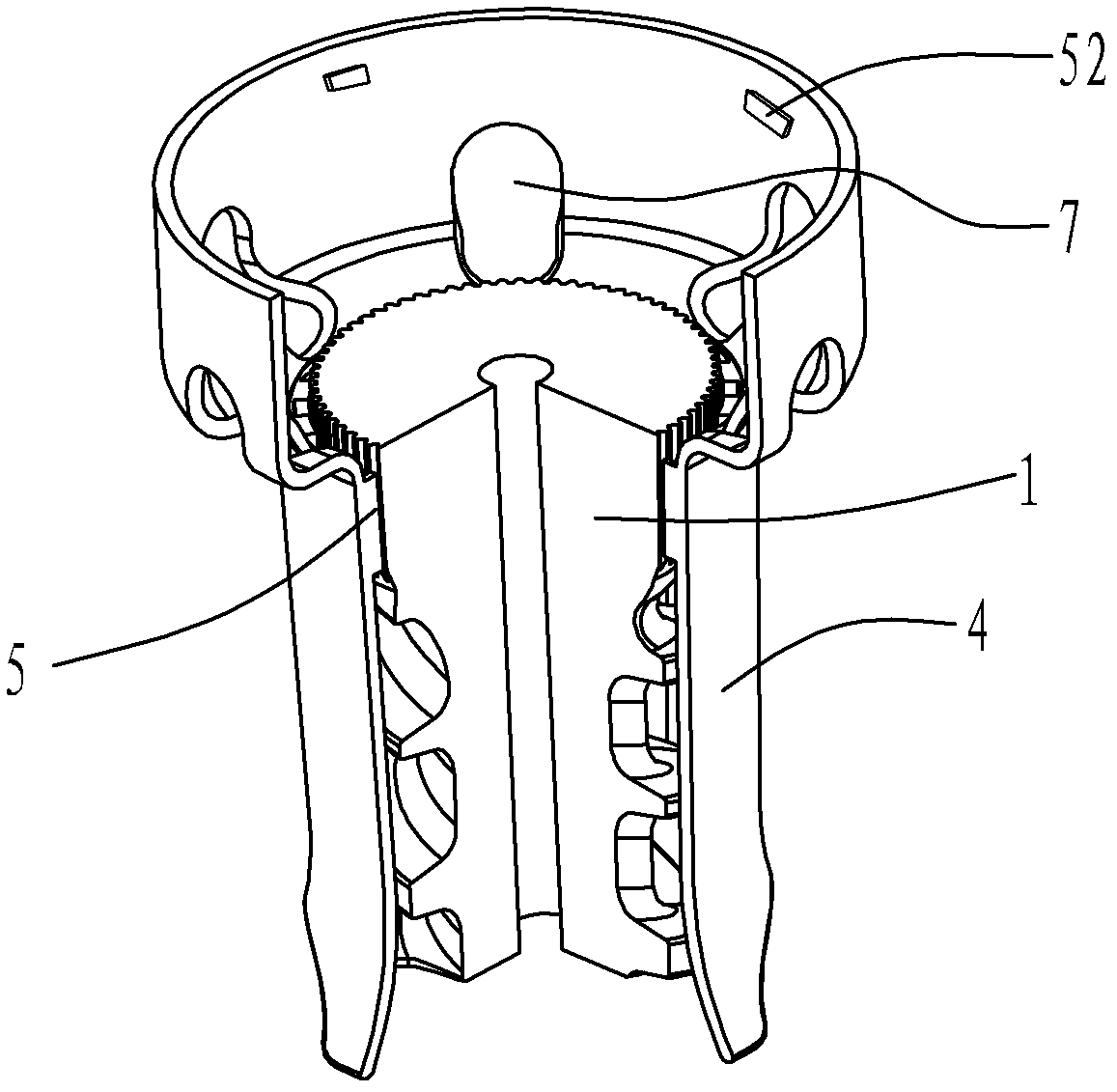
[0062] The liquid flow driving device 2 is a thread that can generate liquid flow driving when rotating. The grinding device at least includes a dynamic grinding head 1 and a static grinding head 4 that are combined inside and outside each other and correspond in shape and structure. The working of the dynamic and static grinding heads On the surface, there are respectively movable grinding teeth 3 and static grinding teeth 5 corresponding in structure.

[0063] The trajectory of the thread of the liquid flow driving device 2 is ro...

Embodiment 2

[0084] See attached Figure 16~17 , in this embodiment, the screw thread of the movable grinding head 1 is different from that of the first embodiment, and has the same technical effect as that of the first embodiment in other places, which will not be repeated here.

[0085] In this embodiment, the thread of the movable grinding head 1 is a single-thread design, that is, only one thread in the same screw goes up the rod, and the single-thread pitch ST-D2 of the first thread 42 is 10~ 50. The height ST-H of the thread of the liquid flow driving device 2 is 5-45 mm. Considering the size of the material and the manufacturing process, the optimal thread distance ST-D2 is 40 mm, and the thread height ST-H is 20 mm.

Embodiment 3

[0087] See attached Figure 19~30 , the dynamic grinding head 1 of this embodiment is different from that of Embodiment 1, and has the same technical effect as Embodiment 1 in other places, and will not repeat them here.

[0088] In this embodiment, in order to adapt to different appearance design requirements, and also to reduce the height of the entire grinding part, the movable grinding teeth 3 of the movable grinding head 1 are changed from roughly the same direction as the central axis of the screw to a roughly vertical direction, as shown in Figure 23 As shown, the angle e between the movable grinding teeth 3 and the central axis of the movable grinding head 1 is 0°~85°, so that the contact surface of the grinding part A formed by the moving grinding head 1 and the static grinding head 4 is larger, and at the same time, the height direction is saved. The space, comprehensive crushing effect and better circulating fluidity of soybean milk have an angle e of 75°.

[0089...


PUM


Abstract

The invention belongs to the field of small kitchen appliances, and specifically relates to a soymilk maker, especially a soymilk maker, which includes a dynamic grinding head arranged on a motor shaft, wherein the moving grinding head includes a fluid-driven grinding head provided with at least one thread. device and the movable grinding teeth placed on the upper end of the liquid flow driving device, and the liquid flow driving device is roughly in the shape of a column, a rod or an inverted cone. When making materials, the dynamic grinding head rotates at high speed in the static grinding guide chamber to form a driving liquid flow, which generates a swirling vortex, and the material is swirled into the liquid flow drive device for coarse crushing and further to the dynamic grinding gear for fine grinding. The gap gradually becomes smaller from bottom to top, and at the same time, the grinding process of materials from coarse to fine is realized. The grinding mechanism of the soya-bean milk machine of the present invention has good pulping effect, and the grinding head is easy to process and wear-resistant.

Description

technical field [0001] The invention belongs to the field of small kitchen appliances, in particular to a soybean milk maker, in particular to a grinding mechanism of the soybean milk maker. Background technique [0002] At present, the soybean milk machine has gradually become one of the commonly used appliances in the kitchen of the majority of users, but most of the soybean milk machines currently use the blade-type pulverization method, that is, the motor drives the blade to rotate quickly, and the blade cuts and impacts the material, and finally achieves the effect of pulping. Referring to the traditional technology and practice, the pulp yield of soybeans or other soy products during the grinding process is much better than that of cutting. And the relative taste is also mellow. [0003] Publication No. is " CN10228939A " Chinese Invention Publication Patent discloses a kind of grinding type soya-bean milk machine, bean-carrying cup bottom is provided with inner and o...

Claims


Application Information

Patent Timeline
Patent Type & Authority Patents(China)
IPC IPC(8): A47J31/00A47J31/44A23C11/10
Inventor 蔡才德张锦洲陈世雄湛海耀
Owner ZHEJIANG SHAOXING SUPOR DOMESTIC ELECTRICAL APPLIANCE CO LTD
Why Eureka
Try Eureka